


Cascode Rf Amplifier
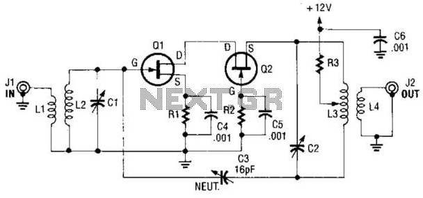
Description: A cascode amplifier using two MOSFETs is illustrated in the diagram. L2C1 and L3C2 resonate at the operating frequency. The circuit offers advantages such as high gain, low noise figure (NF), and excellent linearity. Q1 and Q2 can be either MPF102 or 2N4416.
The cascode amplifier configuration is a well-regarded topology in analog circuit design, particularly known for its ability to enhance performance metrics such as gain, bandwidth, and linearity while reducing noise. In this specific design, two MOSFETs are utilized, which allows for improved control over the output characteristics.
The resonant components L2C1 and L3C2 are critical in defining the frequency response of the amplifier. These components form resonant circuits that can be tuned to the desired operating frequency, ensuring optimal performance within the specified range. The resonant frequency is determined by the values of the inductors (L) and capacitors (C) used, following the standard formula for resonance: f = 1 / (2π√(LC)).
The choice of MOSFETs, specifically the MPF102 or 2N4416, is significant as these devices are characterized by their low threshold voltage and high transconductance, which contribute to the overall gain and efficiency of the amplifier. The cascode arrangement minimizes the Miller effect, which enhances the bandwidth and stability of the amplifier.
Furthermore, the low noise figure is a critical advantage in applications where signal integrity is paramount, such as in RF amplification or sensitive analog signal processing. The configuration's excellent linearity ensures that the output signal remains faithful to the input, making it suitable for high-fidelity applications.
In summary, the described cascode amplifier circuit effectively combines the advantages of MOSFET technology with resonant circuit design to achieve superior performance metrics, making it a valuable choice for a variety of electronic applications. A cascode amplifier using two MOSFETs is shown in the diagram. L2C1 and L3C2 resonate to the frequency in use. The cir cuit has the advantage of good gain, low NF, and excellent linearity. Ql and Q2 can be MPF102 or 2N4416.
The cascode amplifier configuration is a well-regarded topology in analog circuit design, particularly known for its ability to enhance performance metrics such as gain, bandwidth, and linearity while reducing noise. In this specific design, two MOSFETs are utilized, which allows for improved control over the output characteristics.
The resonant components L2C1 and L3C2 are critical in defining the frequency response of the amplifier. These components form resonant circuits that can be tuned to the desired operating frequency, ensuring optimal performance within the specified range. The resonant frequency is determined by the values of the inductors (L) and capacitors (C) used, following the standard formula for resonance: f = 1 / (2π√(LC)).
The choice of MOSFETs, specifically the MPF102 or 2N4416, is significant as these devices are characterized by their low threshold voltage and high transconductance, which contribute to the overall gain and efficiency of the amplifier. The cascode arrangement minimizes the Miller effect, which enhances the bandwidth and stability of the amplifier.
Furthermore, the low noise figure is a critical advantage in applications where signal integrity is paramount, such as in RF amplification or sensitive analog signal processing. The configuration's excellent linearity ensures that the output signal remains faithful to the input, making it suitable for high-fidelity applications.
In summary, the described cascode amplifier circuit effectively combines the advantages of MOSFET technology with resonant circuit design to achieve superior performance metrics, making it a valuable choice for a variety of electronic applications. A cascode amplifier using two MOSFETs is shown in the diagram. L2C1 and L3C2 resonate to the frequency in use. The cir cuit has the advantage of good gain, low NF, and excellent linearity. Ql and Q2 can be MPF102 or 2N4416.

Power Supply for Amlifiers [B]
Proposed power supply for amplifier 100W v-mosfet is what appears in the above form. It has separated supply for the various stages of supply, stage for power, stage for control, supply for preamplifier and for stage of protection. Whoever wants...

Bandswitched Grid Dip Meter
This circuit is designed for checking resonances in tuned circuits, antennas, and similar applications, covering a frequency range of 2 to 20 MHz. Q1 acts as an oscillator that can be tuned across this range using capacitor C1 and band-switched...

300w Mosfet Linear Amplifier For 50 Mhz
The converter depicted in Figure 1 utilizes a component from the PeakSwitch family (U1, a PKS606YN) to operate a 36 W motor, capable of handling startup and load transition peaks of up to 72 W. The motor speed can be...

RECEIVER BUILDING BLOCKS
This amplifier has about 20dB of gain, bandwidth of 100MHz and noise figure of about 7dB. The output transformer is 8 turns bifilar wound on a ferrite core. Use a medium power UHF transistor 2N5109, 2N3866, 2N4427 or similar. The...

Simple Rf Test Oscillator Circuit
A simple oscillator for intermediate frequency (IF) alignment at 455 kHz can be useful in field testing or in scenarios where a standard signal generator is available. The inductor (L1) should resonate at the desired output frequency with the series...
25 Watt MosFet Amplifier
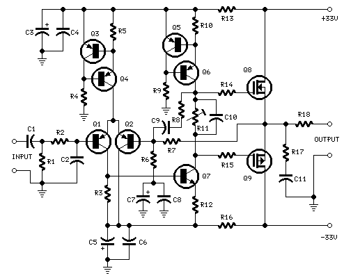
High Quality simple design No need for a preamplifier Can be directly connected to CD players, tuners and tape recorders. Simply add a 10K Log potentiometer (dual gang for stereo) and a switch to cope with the various sources you...
amplifier timer circuit schematic
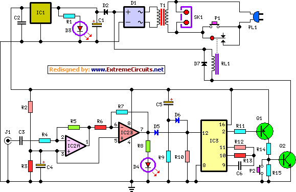
This circuit deactivates an amplifier or any connected device when a low-level audio signal at its input is absent for at least 15 minutes. By pressing P1, the device is powered on, supplying power to any appliance connected to SK1....

300 watt 1200 watt MOSFET Amplifier for professionals only
When an amplifier with high watt power is required, this circuit is most suitable for applications such as concerts, theaters, and festivals.
This high-power amplifier circuit is designed to deliver significant output power, making it ideal for large-scale audio applications where...

Amplifier Timer Circuit Schematic
This circuit turns off an amplifier or any other device when a low-level audio signal fed to its input is absent for at least 15 minutes. Pressing P1 switches the device on, supplying power to any appliance connected to SK1....