


CB transmitter
#CB transmitter
#copper coils
#aerial
#channel switch
#RF circuit
#wireless transmission
#antenna
#radio communication
#transmitter design
#perjstrofjkoy core

Description: L1 and L2 are copper wires with a diameter of 0.4 mm, wrapped in a plastic support with a diameter of 6-7 mm, featuring a perjstrofjkoy core. For L1, 13 coils are wrapped, while for L2, 4 coils are wrapped (similar to the receptor CB). ANT1 is an aerial for CB; for initial trials, a piece of wire a few meters long is sufficient, but it is recommended to connect a proper aerial to avoid excessive stagnation and prevent damage to the transmitter. S2 is a switch for selecting channels. There are multiple locations for connecting the desired channels. It is better if S2 is mechanically linked to S1 of the receptor for simultaneous channel changes. A microphone is connected, and when speaking, the multimeter should indicate an increase of approximately 30-35% if everything is functioning correctly.
L1 and L2 serve as the primary inductors in the circuit, providing necessary magnetic coupling for signal transmission. The choice of copper as the wire material ensures minimal resistive losses, while the specified diameter allows for efficient inductance values to be achieved. The plastic support serves to maintain the integrity of the coil structure, preventing any deformation that could affect performance.
The aerial (ANT1) is crucial for effective transmission and reception of CB signals. While a temporary wire may suffice for initial testing, utilizing a properly designed aerial is essential for optimal performance, minimizing signal degradation, and protecting the transmitter from potential overload conditions caused by reflections or standing waves.
S2, the channel selection switch, allows the user to choose between different operational frequencies. The mechanical linkage to S1 enhances user experience by allowing simultaneous channel changes, which is particularly useful in dynamic communication environments.
The microphone connection is integral to the system, providing audio input for transmission. The multimeter serves as a diagnostic tool, enabling the user to monitor output levels. An increase in the multimeter reading by 30-35% during operation indicates proper functionality of the audio input stage, suggesting that the system is effectively converting sound waves into electrical signals for transmission. This feedback loop is essential for ensuring reliable communication in practical applications.L1, L2 Wires of coper (smaltwme`na) with diameter 0, 4mm wrapped in plastic support of diameter 6-7mm of perjstrofjkoy` core. For the L1 you wrap 13 coils. For the L2 you wrap 4 coils. (As in the receptor CB. ) ANT1 Aerial for CB (For the trials is enough a piece wire of few metres but better connects a regular aerial so that does not have many stagnantly and burns the transmitter).
S2 Switch of choice of channel. It has so much places, those who also the channels that you want pja`nete. (Kaly`tera he is mechanically connected with the S1 of receptor for simultaneous change of channels). 4. We connect the microphone and speaking we observe the clue in the multimeter. If all have become right will be supposed the tendency, speaking, to go up roughly 30-35%.
L1 and L2 serve as the primary inductors in the circuit, providing necessary magnetic coupling for signal transmission. The choice of copper as the wire material ensures minimal resistive losses, while the specified diameter allows for efficient inductance values to be achieved. The plastic support serves to maintain the integrity of the coil structure, preventing any deformation that could affect performance.
The aerial (ANT1) is crucial for effective transmission and reception of CB signals. While a temporary wire may suffice for initial testing, utilizing a properly designed aerial is essential for optimal performance, minimizing signal degradation, and protecting the transmitter from potential overload conditions caused by reflections or standing waves.
S2, the channel selection switch, allows the user to choose between different operational frequencies. The mechanical linkage to S1 enhances user experience by allowing simultaneous channel changes, which is particularly useful in dynamic communication environments.
The microphone connection is integral to the system, providing audio input for transmission. The multimeter serves as a diagnostic tool, enabling the user to monitor output levels. An increase in the multimeter reading by 30-35% during operation indicates proper functionality of the audio input stage, suggesting that the system is effectively converting sound waves into electrical signals for transmission. This feedback loop is essential for ensuring reliable communication in practical applications.L1, L2 Wires of coper (smaltwme`na) with diameter 0, 4mm wrapped in plastic support of diameter 6-7mm of perjstrofjkoy` core. For the L1 you wrap 13 coils. For the L2 you wrap 4 coils. (As in the receptor CB. ) ANT1 Aerial for CB (For the trials is enough a piece wire of few metres but better connects a regular aerial so that does not have many stagnantly and burns the transmitter).
S2 Switch of choice of channel. It has so much places, those who also the channels that you want pja`nete. (Kaly`tera he is mechanically connected with the S1 of receptor for simultaneous change of channels). 4. We connect the microphone and speaking we observe the clue in the multimeter. If all have become right will be supposed the tendency, speaking, to go up roughly 30-35%.

915-MHz antenna monopole
The Tab antenna is a folded monopole that you miniaturize by forming it into an inverted L with a downward bend at the end. You can solder it perpendicular to a pc board or build it as part of a...

Q- Multiplying Loop Antenna
This circuit is designed to be used in conjunction with the standard 4 foot square loop used in MW for long distance reception.
The described circuit is intended for use with a standard 4-foot square loop antenna, optimized for medium wave...

Antenna Booster for FM AM and SW Receiver
This AM/FM antenna booster circuit amplifies the broadband signal from the antenna. This antenna booster is designed to work for FM, AM, and SW receivers.
The AM/FM antenna booster circuit is an essential component for enhancing radio reception across various...
an active whip receiving antenna
In the pursuit of effective small antennas, an active whip antenna was constructed. This compact vertical antenna is linked to a preamplifier, which serves to convert the high impedance of the 50-ohm receiver and coaxial cable. Various designs exist for...

Antenna Circuits / Schematics
This document presents plans for a simple ground plane antenna that is effective in the FM band (88-108 MHz). It is constructed from a small plastic disk. The 6 x 6 loop antenna, designed by Graham Maynard, is highlighted as...

ANTENNA DESIGN FOR FM TRANSMITTER
Two aluminum rods, each of length "L" in meters, are connected through an insulator as illustrated in the figure. A 75-ohm cable is fed from the center, similar to a conventional TV antenna.
This configuration describes a basic antenna system utilizing...

Antennas for HAM transmitters
Antenna is the means by which a wireless operator puts his signal into the space and also through which he picks up the signals of the stations with which he wants to communicate. Hence after having a good Receiver and...

Antenna ground loop Isolator
A ground loop in your AV system caused by antenna connection or TV cable is very common if you have your computer connected to the same system. This type of ground loop problem can be solved by using suitable isolation...

Active Antenna
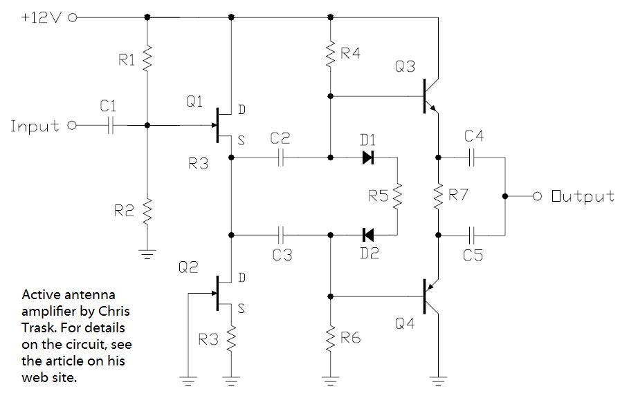
Antennas that are much shorter than 1/4 wavelength present a very small and highly relative impedance that is dependent on the received frequency. It is difficult to match impedances over a decade of frequency coverage. Instead, input stage Q1 is...