


CRYSTAL RADIO SET
#crystal radio
#AM radio
#passive circuit
#antenna
#radio receiver
#wireless
#energy harvesting
#old time radio
#experimenter circuit
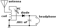
Description: Here is the schematic diagram for a very basic crystal radio set without any particular embellishments. This basic old time radio uses no power other than that provided by the transmitting antenna from the radio station. Free power from the sky eh!. It truly is a marvel!. As a matter of interest, some amateurs and experimenters living in the vicinity of high powered AM Radio transmitters have literally used crystal radio sets to trickle charge their batteries. Now THAT is real COOL! If the demand exists we will do it too!.
The crystal radio set is a simple yet effective device that operates without an external power source, utilizing the energy from radio waves received by its antenna. The primary components of a basic crystal radio include an antenna, a diode (often a crystal detector), a tuning coil, a capacitor, and a high-impedance earphone.
The antenna captures radio frequency signals, which are then fed into the tuning coil. The tuning coil, in conjunction with the variable capacitor, forms a resonant circuit that allows the user to select a specific frequency for reception. By adjusting the capacitor, the circuit can be tuned to the desired radio station's frequency, effectively filtering out unwanted signals.
The diode serves as a rectifier, converting the alternating current (AC) signal received from the antenna into direct current (DC). This rectified signal is then sent to the earphone, which converts the electrical energy into sound waves that can be heard by the listener. The earphone in a crystal radio set is typically a high-impedance type, as the circuit does not provide significant power.
In some cases, enthusiasts have modified their crystal radios to include additional components, such as a small battery or supercapacitor, allowing them to store energy harvested from nearby high-powered AM transmitters. This enables the radio to charge batteries or power small devices, showcasing the versatility and ingenuity associated with crystal radio technology.
Overall, the simplicity of the crystal radio set not only serves as an educational platform for understanding basic electronics but also highlights the fascinating principles of radio wave transmission and energy harvesting.Here is the schematic diagram for a very basic crystal radio set without any particular embellishments. This basic old time radio uses no power other than that provided by the transmitting antenna from the radio station.
Free power from the sky eh!. It truly is a marvel!. As a matter of interest, some amateurs and experimenters living in the vicinity of high powered AM Radio transmitters have literally used crystal radio sets to trickle charge their batteries. Now THAT is real COOL! If the demand exists we will do it too!.
The crystal radio set is a simple yet effective device that operates without an external power source, utilizing the energy from radio waves received by its antenna. The primary components of a basic crystal radio include an antenna, a diode (often a crystal detector), a tuning coil, a capacitor, and a high-impedance earphone.
The antenna captures radio frequency signals, which are then fed into the tuning coil. The tuning coil, in conjunction with the variable capacitor, forms a resonant circuit that allows the user to select a specific frequency for reception. By adjusting the capacitor, the circuit can be tuned to the desired radio station's frequency, effectively filtering out unwanted signals.
The diode serves as a rectifier, converting the alternating current (AC) signal received from the antenna into direct current (DC). This rectified signal is then sent to the earphone, which converts the electrical energy into sound waves that can be heard by the listener. The earphone in a crystal radio set is typically a high-impedance type, as the circuit does not provide significant power.
In some cases, enthusiasts have modified their crystal radios to include additional components, such as a small battery or supercapacitor, allowing them to store energy harvested from nearby high-powered AM transmitters. This enables the radio to charge batteries or power small devices, showcasing the versatility and ingenuity associated with crystal radio technology.
Overall, the simplicity of the crystal radio set not only serves as an educational platform for understanding basic electronics but also highlights the fascinating principles of radio wave transmission and energy harvesting.Here is the schematic diagram for a very basic crystal radio set without any particular embellishments. This basic old time radio uses no power other than that provided by the transmitting antenna from the radio station.
Free power from the sky eh!. It truly is a marvel!. As a matter of interest, some amateurs and experimenters living in the vicinity of high powered AM Radio transmitters have literally used crystal radio sets to trickle charge their batteries. Now THAT is real COOL! If the demand exists we will do it too!.

Antenna ground loop Isolator
A ground loop in your AV system caused by antenna connection or TV cable is very common if you have your computer connected to the same system. This type of ground loop problem can be solved by using suitable isolation...

Homemade wireless remote control circuit diagram
The homemade wireless remote control circuit diagram illustrates a motor remote control transmitter circuit. The circuit utilizes a 555 timer along with resistors R1, R2, RP1, diodes VD1, VD2, and capacitor C1 to create a variable duty cycle astable oscillator....

Wireless Fm Microphone
A simple FM wireless microphone utilizes a single BC183C transistor as an audio amplifier, with the option to substitute it with a 2N3565. The transistor Q1 functions as an oscillator that is frequency-modulated by the signal from Q1. Other transistors...

5 Tube AC/DC Radio Receiver
Nearly all AM radio manufacturers utilized this specific circuit from approximately 1948 to 1963. There is a growing interest in collecting these radios as antiques. Credit for the creator of this figure and caption is sought, but the source of...

Booster Antenna Circuit 550Khz to 1650Khz
This is a booster antenna circuit designed for frequencies ranging from 550 kHz to 1650 kHz, aimed at amplifying signals received from a telescopic antenna. It covers the medium waveband within this frequency range. To drive low impedance (50 ohm)...

Antenna Low Power RF & Wireless Connectivity
The "green area" is designated for the placement of the TRF7970A's antenna, which should be connected between two 0-ohm resistors. The antenna can be constructed step by step following the guidelines in the document "Antenna Matching for the TRF7960 RFID...

regenerative radio receivers
A regenerative radio receiver is known for its simplicity, weak signal reception, inherent noise-limiting and automatic gain control (AGC) action, as well as its immunity to overloading and spurious responses. The regenerative radio receiver, often referred to as "regen," operates...

Wireless IR Headphones circuit
This wireless infrared (IR) headphones circuit project enables the transmission of audio signals through an infrared connection. The circuit consists of two main components: a transmitter and a receiver. Unlike radio frequency (RF) transmitters, both parts of this application must...
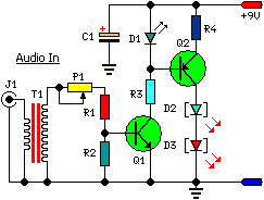
A Low Power Wireless Audio Power Amplifier circuit
This low-cost project enables audio reproduction from a television without disturbing others. It eliminates the need for wired connections between the TV and loudspeakers. Instead, it utilizes invisible infrared light to transmit audio signals from the TV to the loudspeakers....