


CW Radio with Tubes

Description: For this radio, which I repaired for someone, I made this DIY VL1. Later I found the real tube.
The circuit described involves a DIY VL1 radio project, which suggests a focus on vacuum tube technology. The VL1 likely refers to a specific type of vacuum tube or a particular circuit design intended for radio frequency applications. In constructing a DIY radio using vacuum tubes, several key components and design considerations are typically involved.
The primary components of a vacuum tube radio circuit include the vacuum tube itself, which functions as an amplifier or oscillator, and passive components such as resistors, capacitors, and inductors that help shape the signal. The power supply must be carefully designed to provide the necessary voltages for the tube operation, typically involving high voltage for the anode and lower voltages for the filament.
In the context of a radio receiver, the circuit may include an antenna input for capturing radio signals, a tuning circuit for selecting the desired frequency, and a detector stage for demodulating the audio signal from the RF carrier. Additionally, output stages may involve further amplification to drive a speaker or headphones.
When designing such a circuit, attention must be paid to component ratings, especially regarding high voltage and current levels associated with vacuum tubes. Proper layout and shielding are also critical to minimize interference and ensure stable operation.
In summary, the DIY VL1 radio project represents a classic approach to radio design, leveraging the unique characteristics of vacuum tubes to create a functional radio receiver. The eventual discovery of the original tube indicates a potential enhancement to the project, allowing for improved performance or authenticity in the radio's operation.For this radio, which I repaired for someone, I made this DIY VL1. Later I found the real tube.
The circuit described involves a DIY VL1 radio project, which suggests a focus on vacuum tube technology. The VL1 likely refers to a specific type of vacuum tube or a particular circuit design intended for radio frequency applications. In constructing a DIY radio using vacuum tubes, several key components and design considerations are typically involved.
The primary components of a vacuum tube radio circuit include the vacuum tube itself, which functions as an amplifier or oscillator, and passive components such as resistors, capacitors, and inductors that help shape the signal. The power supply must be carefully designed to provide the necessary voltages for the tube operation, typically involving high voltage for the anode and lower voltages for the filament.
In the context of a radio receiver, the circuit may include an antenna input for capturing radio signals, a tuning circuit for selecting the desired frequency, and a detector stage for demodulating the audio signal from the RF carrier. Additionally, output stages may involve further amplification to drive a speaker or headphones.
When designing such a circuit, attention must be paid to component ratings, especially regarding high voltage and current levels associated with vacuum tubes. Proper layout and shielding are also critical to minimize interference and ensure stable operation.
In summary, the DIY VL1 radio project represents a classic approach to radio design, leveraging the unique characteristics of vacuum tubes to create a functional radio receiver. The eventual discovery of the original tube indicates a potential enhancement to the project, allowing for improved performance or authenticity in the radio's operation.For this radio, which I repaired for someone, I made this DIY VL1. Later I found the real tube.

SENSITIVE RF VOLTMETER
This schematic illustrates a peak-reading diode voltmeter that is powered by two amplification stages. A 100 µF capacitor is utilized to create a substantial time constant, which ensures effective damping of the meter. The restricted differential output voltage, combined with...
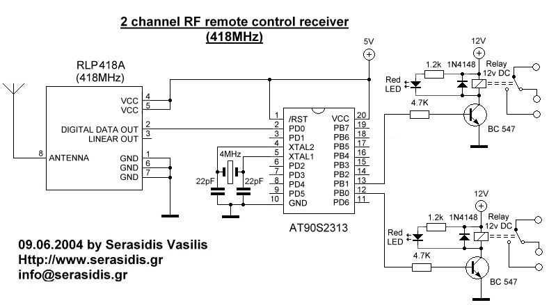
2 channel RF remote control
The basic small-range remote controls are Infrared and RF (Radio Frequency). One of the weaknesses of Infrared is that the signal cannot pass through walls. Therefore, to control a garage door, an RF remote control is necessary. The circuit (transmitter...

Radio Frequency Circuits
This page is provided to the domain owner free by Sedo's Domain Parking. Disclaimer: The domain owner and Sedo maintain no relationship with third-party advertisers. References to any specific service or trademark are not controlled by Sedo or the domain...

ham radio circuit audio filter
This design circuit functions to filter out interference signals, ensuring that the signal received from a Morse code station is distinct. The circuit utilizes the earliest mode of radio communications, which employs Morse Code on a continuous wave carrier (CW)...

Taylor Source Follower
A setup was created using 22 used octal tubes, specifically 6.3-volt, 600mA controlled-warm-up tubes (predominantly 6SN7s), along with 22 octal tube sockets and an old extension cord. The sockets were wired in series and connected to a wall socket, resulting...

Rf power meter
The reflectometer (SWR power meter) operates across three decades, ranging from 100 kHz to 100 MHz. It can be designed to handle RF power levels as low as 500 mW and up to 500 watts.
The reflectometer, also known as a...

Simple Ham Radio Circuit Audio Filter With 741 IC
This circuit will filter out interference signals and ensure that the signal received from the Morse code station stands out.
The described circuit functions as a signal processing system specifically designed to enhance the clarity of Morse code transmissions by minimizing...

Jammer circuit
The frequency jammer operates by generating interfering RF noise centered around a 2.45 GHz carrier frequency. As the power of this noise increases, the signal-to-noise ratio of the wireless communication channel decreases, leading to a higher bit error rate until...

Remote ControlCircuit Through RF Without Microcontroller
This circuit illustrates a remote control circuit diagram using RF technology without the use of a microcontroller. Features include a simple remote control circuit that operates via radio frequency.
The remote control circuit operates by transmitting signals through radio waves, enabling...