


DIY FrSky GPS Telemetry Sensor with Logging

Description: Following last year's rediscovery of radio-controlled flight, there is a growing interest in the hacking and modification potential of the budget-friendly 9-channel FlySky FS-TH9X transmitter (also marketed as Turnigy/Eurgle, etc.). The original 2.4GHz RF module and firmware are quite functional, making this device a capable tool considering its price. However, it becomes even more impressive when upgraded with open-source firmware and a FrSky telemetry-capable RF module replacement. With a modest investment and some intermediate-level hardware modifications, this configuration offers features that many high-end, brand-name transmitters lack. During research on RCGroups and related forums, a post by (Jo)Hannes, known as der-frickler, detailed a custom GPS module he created for the FrSky Telemetry Sensor Hub to receive real-time GPS data on the transmitter display, addressing a temporary backorder issue with the original FrSky GPS sensor. This inspired the development of a similar setup to display GPS data (such as altitude and speed) on the transmitter, allowing pilots to maintain focus on their models during flight. Additionally, it provides a log of GPS data for later analysis and visualization. Utilizing the inexpensive Mediatek MT3326 GPS receiver, paired with a SparkFun OpenLog data logger, captures the 9600 baud NMEA output sequence from the GPS chip and stores it on a micro-SD card. The circuit design follows the reference sheet for the MediaTek chip and features a corresponding SMD-based layout. The primary components include the MediaTek chip, the OpenLog breakout board, an LM3940 3.3V regulator for the GPS chip, a GPS fix LED indicator, and a battery backup for the GPS almanac using a CR2032 Li battery. Although the initial plan was to use an AMS1117 regulator due to its less stringent capacitor requirements, the LM3940 was utilized instead. The CR2032 battery is secured to the bottom of the circuit board using hot glue. The OpenLog board requires no additional configuration, as its standard firmware settings are compatible with real-time SD card logging.
The schematic design for the described GPS module setup involves several key components integrated to achieve the desired functionality. The MediaTek MT3326 GPS receiver serves as the core element, responsible for acquiring satellite signals and providing positional data in NMEA format. The 3.3V LM3940 voltage regulator ensures that the GPS module receives a stable power supply, crucial for consistent performance during operation. The GPS fix LED indicator is connected to the output of the MediaTek chip, providing visual feedback on the GPS status, which can be particularly useful during flight.
The SparkFun OpenLog data logger is connected directly to the GPS module to capture the NMEA output. It operates at a baud rate of 9600, which matches the output of the MediaTek chip, ensuring seamless data logging onto the micro-SD card. The OpenLog board is designed to handle various data formats, making it adaptable for different applications beyond GPS data logging.
The circuit layout can be designed using a standard PCB design software, ensuring proper placement of components to minimize interference and optimize signal integrity. The SMD components should be placed strategically to reduce the overall footprint of the board while maintaining accessibility for soldering and connections. The CR2032 battery holder should be positioned to allow easy replacement of the battery, ensuring that the GPS almanac can be retained even when the main power is disconnected.
Overall, this setup not only enhances the functionality of the FlySky FS-TH9X transmitter but also provides an engaging project for electronics enthusiasts interested in radio-controlled flight and telemetry systems. The integration of GPS data into the transmitter display and the ability to log this data for analysis opens up new possibilities for improving flight techniques and understanding the dynamics of model aircraft.Following last year`s rediscovery of radio controlled flight, I`ve recently become enamored with the hacking/mod potential of the downright bargain priced 9-channel FlySky FS-TH9X transmitter (also sold as Turnigy/Eurgle etc). The original 2. 4GHz RF module and firmware are quite useable, already making this a fairly capable piece of kit considerin
g the price. However, it becomes a truly remarkable tool when equipped with an open source replacement firmware and the FrSky telemetry capable RF module replacement. For a very moderate investment and with the willingness to do a few intermediate level hardware modifications, you end up with a package providing features that even many top-of-the line, brand name transmitters are lacking.
While going through the huge thread over at RCGroups and some related content, I stumbled upon a post by (Jo)Hannes a. k. a. der-frickler detailing a custom GPS module he built for the FrSky Telemetry Sensor Hub - in order to receive real-time GPS data in his transmitter display and overcoming a temporary backorder situation with the original/OEM FrSky GPS sensor.
I figured it would be nice to build upon that quite inspired hack and not only to be able to view the corresponding GPS data (such as height and speed) in the transmitter display - averting your eyes from your model while you are flying can be rather tricky if not downright disastrous during high speed low altitude sweeps - but also to have a log of all collected GPS data for later analysis and visualization. A bit of research led me to the solution of using the same inexpensive Mediatek MT3326 GPS receiver used by Hannes, paired with a SparkFun OpenLog data logger capable of capturing the 9600 baud NMEA output sequence of the GPS chip and writing it onto a micro-SD card.
Following the reference sheet for the MediaTek chip resulted in a fairly straight forward circuit design and a corresponding SMD based reference layout: I apologize for the messiness, PCB layout and hardware design is not one of my fortes. The main components are the already mentioned MediaTek chip and OpenLog breakout board, complemented by an LM3940 3.
3V regulator for the GPS chip, a GPS fix LED indicator, and a battery backup for the GPS almanac based on a simple CR2032 Li battery. My initial intention was to use an AMS1117 regulator with it`s less stringent capacitor requirements but the 3940 was all I had at hand.
The result can be seen below, the CR2032 battery is hot glued to the bottom of the circuit board (not visible). The OpenLog board does not need any additional configuration. The standard firmware settings of the board matching real-time SD card
The schematic design for the described GPS module setup involves several key components integrated to achieve the desired functionality. The MediaTek MT3326 GPS receiver serves as the core element, responsible for acquiring satellite signals and providing positional data in NMEA format. The 3.3V LM3940 voltage regulator ensures that the GPS module receives a stable power supply, crucial for consistent performance during operation. The GPS fix LED indicator is connected to the output of the MediaTek chip, providing visual feedback on the GPS status, which can be particularly useful during flight.
The SparkFun OpenLog data logger is connected directly to the GPS module to capture the NMEA output. It operates at a baud rate of 9600, which matches the output of the MediaTek chip, ensuring seamless data logging onto the micro-SD card. The OpenLog board is designed to handle various data formats, making it adaptable for different applications beyond GPS data logging.
The circuit layout can be designed using a standard PCB design software, ensuring proper placement of components to minimize interference and optimize signal integrity. The SMD components should be placed strategically to reduce the overall footprint of the board while maintaining accessibility for soldering and connections. The CR2032 battery holder should be positioned to allow easy replacement of the battery, ensuring that the GPS almanac can be retained even when the main power is disconnected.
Overall, this setup not only enhances the functionality of the FlySky FS-TH9X transmitter but also provides an engaging project for electronics enthusiasts interested in radio-controlled flight and telemetry systems. The integration of GPS data into the transmitter display and the ability to log this data for analysis opens up new possibilities for improving flight techniques and understanding the dynamics of model aircraft.Following last year`s rediscovery of radio controlled flight, I`ve recently become enamored with the hacking/mod potential of the downright bargain priced 9-channel FlySky FS-TH9X transmitter (also sold as Turnigy/Eurgle etc). The original 2. 4GHz RF module and firmware are quite useable, already making this a fairly capable piece of kit considerin
g the price. However, it becomes a truly remarkable tool when equipped with an open source replacement firmware and the FrSky telemetry capable RF module replacement. For a very moderate investment and with the willingness to do a few intermediate level hardware modifications, you end up with a package providing features that even many top-of-the line, brand name transmitters are lacking.
While going through the huge thread over at RCGroups and some related content, I stumbled upon a post by (Jo)Hannes a. k. a. der-frickler detailing a custom GPS module he built for the FrSky Telemetry Sensor Hub - in order to receive real-time GPS data in his transmitter display and overcoming a temporary backorder situation with the original/OEM FrSky GPS sensor.
I figured it would be nice to build upon that quite inspired hack and not only to be able to view the corresponding GPS data (such as height and speed) in the transmitter display - averting your eyes from your model while you are flying can be rather tricky if not downright disastrous during high speed low altitude sweeps - but also to have a log of all collected GPS data for later analysis and visualization. A bit of research led me to the solution of using the same inexpensive Mediatek MT3326 GPS receiver used by Hannes, paired with a SparkFun OpenLog data logger capable of capturing the 9600 baud NMEA output sequence of the GPS chip and writing it onto a micro-SD card.
Following the reference sheet for the MediaTek chip resulted in a fairly straight forward circuit design and a corresponding SMD based reference layout: I apologize for the messiness, PCB layout and hardware design is not one of my fortes. The main components are the already mentioned MediaTek chip and OpenLog breakout board, complemented by an LM3940 3.
3V regulator for the GPS chip, a GPS fix LED indicator, and a battery backup for the GPS almanac based on a simple CR2032 Li battery. My initial intention was to use an AMS1117 regulator with it`s less stringent capacitor requirements but the 3940 was all I had at hand.
The result can be seen below, the CR2032 battery is hot glued to the bottom of the circuit board (not visible). The OpenLog board does not need any additional configuration. The standard firmware settings of the board matching real-time SD card

12ft GPS Wall Clock
A discussion was held regarding the creation of a 6-foot tall alarm clock, modeled after a Timex faceplate. Initially perceived as an impractical idea, the project faced challenges that led to its suspension. However, the discovery of pre-packaged LED light...

GPS Synchronised Clock
This project replaces the electronics in a standard quartz wall clock with a circuit that uses GPS satellites to obtain precise time.
The proposed project involves the modification of a conventional quartz wall clock by integrating a GPS-based timing circuit. The...
RF Module Interfacing Circuit Example
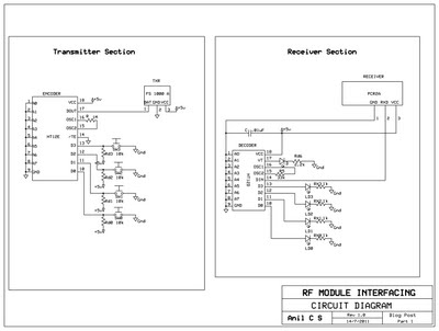
This document presents a circuit example for interfacing an RF module using the HT12E/D encoder-decoder pair. The attached circuit can be utilized for data transmission via the RF module, which is designed for single-channel operation, allowing only serial data transfers....
Remote tuning transmitter
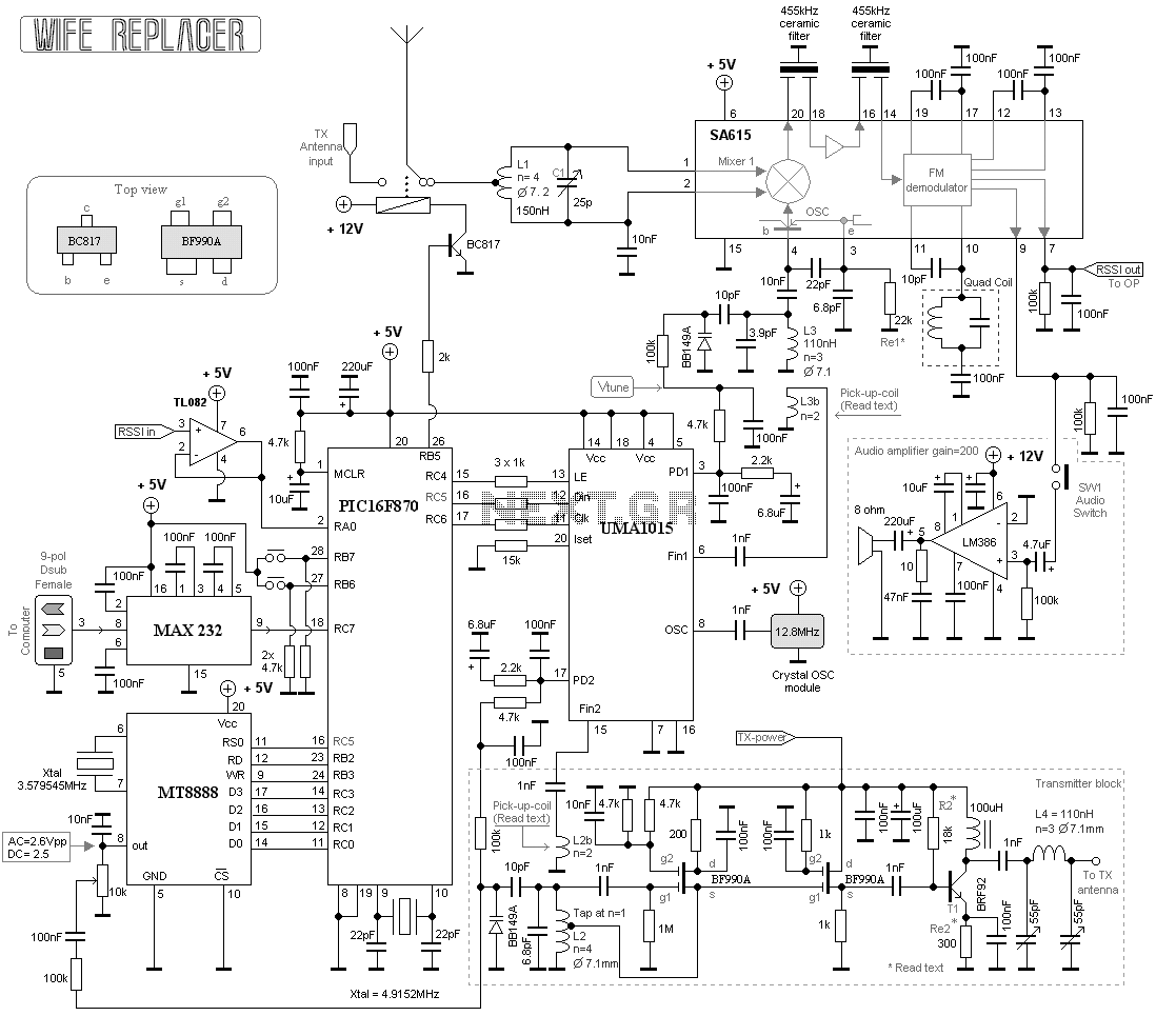
This project consists of a wide range receiver and one transmitter. Together they will form a unit which will help you tuning your homebrewed transmitter. The most difficult part of homebrewing is the tuning part of the transmitters. How should...

80 Watt stereo transmitter
This transmitter was designed from the ground up to provide very high sound quality, coupled with excellent frequency stability, reliability, etc. It can be used as a standalone transmitter to serve a medium-sized town, or as an exciter to drive...

Precision QRP Transmitter
This compact transmitter is suitable for less demanding Doppler propagation measurements. It is designed for operation on the 80m band but can be easily adapted for the 40m or 20m bands. The output power is approximately 500mW of unmodulated carrier,...

GPS Receiver RF Block Diagram Based On The MAX2742 IC
The following circuit illustrates the RF block diagram of a GPS receiver. This circuit is based on the MAX2742 integrated circuit. Features include a complete GPS receiver functionality.
The GPS receiver RF block diagram utilizing the MAX2742 IC encompasses several critical...

remote control circuit
The remote control circuit comprises two main components: a transmitter and a receiver. The transmitter circuit is controlled by an NE555 integrated circuit (IC), while the receiver operates based on the frequency of the signal emitted by the transmitter. It...
gps voice interface for wouxun kg uv3d circuit
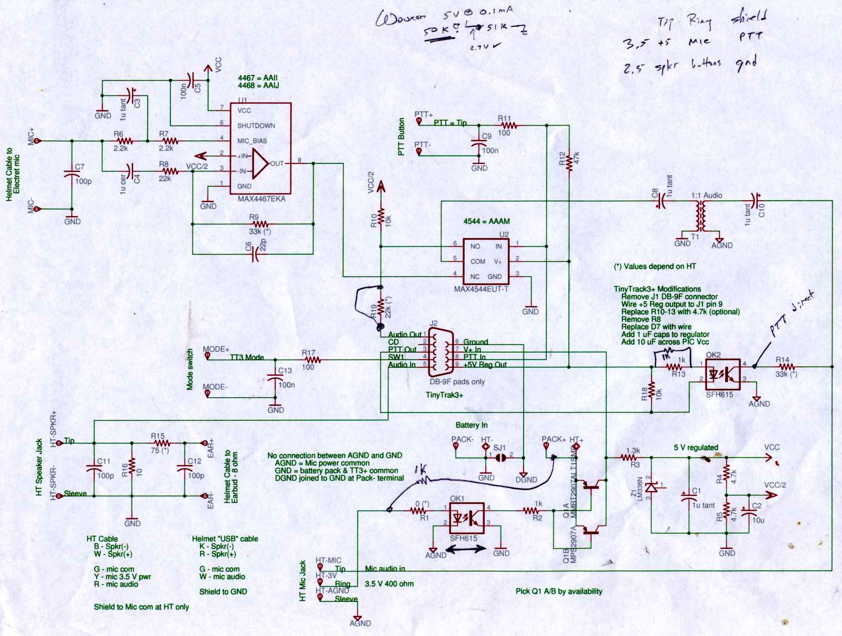
Connect the Byonics TinyTrak 3+ GPS modem, helmet earbud/mic, and external battery pack to the Z-1A, which is incompatible with the Wouxun. The KG-UV3D utilizes the Kenwood HT interface with a single ground for mic, speaker, and PTT functions, eliminating...