


FM Booster~Active FM Antenna Amplifier
#FM booster
#active antenna
#RF preamplifier
#2SC2570
#VHF/UHF
#tuned amplifier
#FM stations
#copper wire
#transistor
#distant reception

Description: This FM booster allows for clear reception of programs from distant FM stations. The circuit features a common-emitter tuned RF preamplifier utilizing the VHF/UHF transistor 2SC2570 (only labeled as C2570 on the transistor body). The input coil L1 is composed of four turns of 20 SWG enameled copper wire, slightly spaced and wound over a 5mm diameter former. It is tapped at the first turn from the ground lead side. Coil L2 is similar to L1 but consists of only three turns.
The FM booster circuit is designed to enhance the reception of FM signals, particularly from stations that are located at a significant distance. The use of the 2SC2570 transistor is crucial as it offers high gain and low noise characteristics, making it suitable for RF amplification applications.
The circuit's architecture employs a common-emitter configuration, which provides a high input impedance and a low output impedance, facilitating efficient signal transfer. The input coil L1 plays a pivotal role in tuning the circuit to the desired frequency, with its four turns allowing for optimal inductance to match the frequency range of FM broadcasts. The slight spacing in the winding of L1 helps in reducing parasitic capacitance, which can adversely affect performance.
The tapping of L1 at the first turn from the ground lead side is a strategic design choice. This configuration allows for better impedance matching and enhances the circuit's selectivity, enabling it to filter out unwanted signals effectively. Coil L2, with its three turns, serves as a secondary inductor that complements L1, further refining the circuit's tuning capabilities.
Overall, this FM booster circuit exemplifies a straightforward yet effective design for improving FM signal reception, making it an essential tool for radio enthusiasts seeking to access distant broadcasts with clarity. Proper assembly and tuning of the coils, along with careful consideration of the transistor's placement and connections, will significantly influence the circuit's performance.This FM booster that can be used to listen to programmes from distant FM stations clearly. The circuit comprises a common-emitter tuned RF preamplifier wired around VHF/UHF transistor 2SC2570. (Only C2570 is annotated on the transistor body. ) Input coil L1 consists of four turns of 20SWG enamelled copper wire (slightly space wound) over 5mm diamet
er former. It is tapped at the first turn from ground lead side. Coil L2 is similar to L1, but has only three turns.
The FM booster circuit is designed to enhance the reception of FM signals, particularly from stations that are located at a significant distance. The use of the 2SC2570 transistor is crucial as it offers high gain and low noise characteristics, making it suitable for RF amplification applications.
The circuit's architecture employs a common-emitter configuration, which provides a high input impedance and a low output impedance, facilitating efficient signal transfer. The input coil L1 plays a pivotal role in tuning the circuit to the desired frequency, with its four turns allowing for optimal inductance to match the frequency range of FM broadcasts. The slight spacing in the winding of L1 helps in reducing parasitic capacitance, which can adversely affect performance.
The tapping of L1 at the first turn from the ground lead side is a strategic design choice. This configuration allows for better impedance matching and enhances the circuit's selectivity, enabling it to filter out unwanted signals effectively. Coil L2, with its three turns, serves as a secondary inductor that complements L1, further refining the circuit's tuning capabilities.
Overall, this FM booster circuit exemplifies a straightforward yet effective design for improving FM signal reception, making it an essential tool for radio enthusiasts seeking to access distant broadcasts with clarity. Proper assembly and tuning of the coils, along with careful consideration of the transistor's placement and connections, will significantly influence the circuit's performance.This FM booster that can be used to listen to programmes from distant FM stations clearly. The circuit comprises a common-emitter tuned RF preamplifier wired around VHF/UHF transistor 2SC2570. (Only C2570 is annotated on the transistor body. ) Input coil L1 consists of four turns of 20SWG enamelled copper wire (slightly space wound) over 5mm diamet
er former. It is tapped at the first turn from ground lead side. Coil L2 is similar to L1, but has only three turns.

2 Transistor LED Flasher
This is a classic 2-transistor astable multivibrator. Many other NPN small signal or switching transistors can be used, including 2N4401, PN2222, or 2N2222 using the circuit on the left. The circuit can also be inverted using PNP transistors such as...

Toy Motor Drivers
This is a reverse-engineered circuit diagram of a one-transistor circuit commonly used to drive permanent magnet DC motors in children's toys. This circuit typically employs the 625mW version of the widely used 8050 or 8550 transistor. It is important to...

audio tone control with 2 transistor
The first BC109C transistor functions as a buffer, offering the circuit an input impedance of approximately 250,000 ohms and a voltage gain just below unity. As the Baxandall tone control circuit is a passive design, it attenuates all audio frequencies....

Class AB Transistor Power Amplifier
Discrete Class AB Transistor Audio Power Amplifier Circuit Diagram. This is a Class AB transistor power amplifier. It is a simple amplifier.
The discrete Class AB transistor audio power amplifier is designed to provide efficient amplification of audio signals while minimizing...

Double transistor low noise of the preamplifier measured by high
The Bong ordinary differential amplifier circuit differs from a standard differential circuit by incorporating a voltage-current conversion circuit, which consists of resistors R and Rl. The operational amplifier (OP amp) includes a voltage divider that subsequently converts the voltage into...
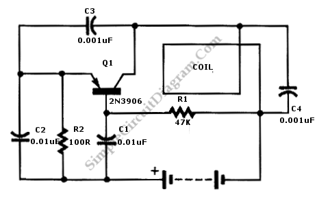
Single Transistor Metal Locator
This is a metal locator circuit designed to detect metal objects. The circuit utilizes an AM radio and a one-transistor oscillator.
The metal locator circuit operates by generating an oscillating signal that can be influenced by the presence of metal. The...
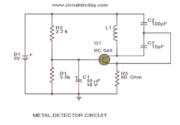
metal detector circuit
This circuit diagram represents a low-cost metal detector utilizing a single transistor circuit in conjunction with an old pocket radio. It operates as a Colpitts oscillator functioning within the medium band frequency range, with the radio tuned to the same...

Nicad Battery Charger circuit
This simple charger utilizes a single transistor as a constant current source. The voltage across the pair of 1N4148 diodes biases the base of the BD140 medium power transistor.
The circuit operates by employing the BD140 transistor to regulate the charging...

Blinker circuit 2
The circuit depicted in Figure 13-4 utilizes triode control. Two transistors, VTi and VTz, are coupled via a capacitor (C) to alternately turn on and off, producing a flashing light effect. The flash frequency is influenced by the capacitance of...