


Fm-transmitter 6
#FM transmitter
#MAX2606
#VCO
#wireless communication
#low-noise
#low-power
#SOT23
#intermediate frequency

Description: This is a single-chip FM transmitter circuit utilizing the Maxim semiconductors IC MAX2606. The MAX2606 is a compact, high-performance intermediate frequency voltage-controlled oscillator (VCO) specifically designed for wireless communication applications. It features a monolithic construction that ensures low noise and low power operation within a compact 6-pin SOT23 package. This low-noise IC incorporates an on-chip varicap diode and feedback capacitances, eliminating the need for external tuning components, making it ideal for portable systems. An external inductor is required to set the oscillation frequency. Additionally, it includes an integrated differential output buffer suitable for driving a mixer or prescaler. The MAX2606 operates from a single supply voltage of +2.8 V to +5.4 V and consumes minimal current, functioning within a frequency range of 45 MHz to 650 MHz. In the circuit, the nominal frequency is set to 100 MHz using inductor L1 (390 nH). The left and right channel audio signals from the source are combined by resistors R3 and R4 and attenuated by potentiometer R2, which serves as a volume control. Potentiometer R1 can be adjusted to select a transmission channel between 88 MHz and 108 MHz. An 80 cm long wire is recommended as the antenna. This circuit exemplifies one of the simplest FM transmitter designs available online. Using only a single transistor and a few passive components, this transmitter can effectively deliver signals up to 50 meters. Transistor Q1 functions as both the modulator and oscillator. Capacitor C2 and inductor L1 create the necessary tank circuit for oscillation. The voice signal to be transmitted is coupled to the base of Q1 via an electret microphone, and the FM signal generated at the collector of Q1 is radiated through the antenna.
Another circuit diagram illustrates an FM transmitter using the IC UPC1651, a wideband UHF Silicon MMIC amplifier. This IC offers a broad frequency response up to 1200 MHz and a power gain of up to 19 dB. It operates from a 5V DC supply. Audio signals captured by the microphone are delivered to the input pin (pin 2) of the IC through capacitor C1, which acts as a noise filter. The modulated FM signal is then available at the output pin (pin 4) of the IC. Inductor L1 and capacitor C3 form the necessary LC circuit for oscillation, with the transmitter frequency adjustable by modifying capacitor C3.
This project represents a straightforward, cost-effective, and engaging endeavor for home experimenters or hobbyists. The simple transmitter can relay speech over short distances, functioning effectively as a basic cordless microphone. The circuit employs two integrated circuits from Maxim: IC1, the MAX4467, serves as an amplifier to elevate the microphone signal to a level suitable for frequency modulation (FM), while IC2 acts as a voltage-controlled oscillator (VCO) equipped with an integrated varactor (varicap diode). The nominal oscillation frequency is determined by inductor L1, which, with a value of 390 nH, yields an oscillation frequency of approximately 100 MHz. For optimal performance, L1 should be a high-Q component, which can be constructed by winding four turns of silver-plated wire around a 10-mm drill bit and stretching it to a length of about 1.5 cm, using wire diameters ranging from 26 SWG (0.5 mm) to 20 SWG (1 mm) without a core. The MAX4467 is a micro-power operational amplifier designed for low voltage applications, providing a 200 kHz gain bandwidth at a supply current of just 24 µA. When paired with an electret microphone, a DC bias for the microphone capsule is necessary. The MAX4467 can deactivate the bias to the microphone when in shutdown mode, conserving several hundred micro-amps of supply current, which is particularly advantageous in low-power scenarios, especially for battery-operated devices like cordless microphones. The MIC-Bias pin offers a switched version of Vcc for the bias components.
A simple telephone transmitter circuit is also described, ideal for transmitting telephone conversations over short distances. The design is straightforward and user-friendly.Here`s a single chip FM transmitter circuit using Maxim semiconductors IC MAX2606. The MAX2606 is a compact, high-performance intermediate frequency VCO specially designed for wireless communication circuits. They have monolithic construction with low-noise and a low-power operation in a compact 6-pin SOT23 packing.
Th1s low-noise IC feature an on -chip varicap diode and feedback capacitances that avoid the need for external tuning components, making the MAX2606 perfect for portable systems. Only an external inductor is needed to set the oscillation frequency. In addition to this, an integrated differential output buffer is also there for driving a mixer or prescaler.
The MAX2606 can be operated from a single +2. 8 V to +5. 4V supply and consumes very less current. The chip can be operated from 45MHz to 650MHz. In the circuit the nominal frequency is set to 100 Mhz by inductor L1, (390nH). The left and right channel audio signals from your source are added by R3 and R4, and attenuated by the POT R2. R2 can be used as a volume control. POT R1 can be used to select a channel of transmission between 88Mhz and 108Mhz. Use 80 cm long wire as the antenna This could be the simplest FM transmitter circuit you can find on the internet.
Only using a single transistor and few passive components, this transmitter can deliver signals up to 50 meters. The transistor Q1 serves as the modulator as well as oscillator. Capacitor C2 and inductor L1 forms the necessary tank circuit for making oscillation. The voice to be transmitted is coupled to the base of Q1 using an electret microphone. The FM signal available at the collector of Q1 is radiated using the antenna Here is the circuit diagram of an FM transmitter using the IC UPC1651.
UPC1651 is a wide band UHF Silicon MMIC amplifier. The IC has a broad frequency response to 1200MHz and power gain up to 19dB. The IC can be operated from 5V DC. The audio signals picked by the microphone are fed to the input pin (pin2) of the IC via capacitor C1. C1 acts as a noise filter. The modulated FM signal will be available at the output pin (pin4) of the IC. Inductor L1 and capacitor C3 forms the necessary LC circuit for creating the oscillations. Frequency of the transmitter can be varied by adjusting the capacitor C3 Here is a very simple, inexpensive and interesting project which provides lot of fun to a home experimenter or hobbyist.
This simple transmitter can transmit speech over a short range. It can be used as a simple cordless microphone. The circuit uses two integrated circuits from Maxim. IC1 a MAX4467, is an amplifier raising the microphone signal to a level suitable for frequency modulation (FM). IC2 is a voltage-controlled oscillator (VCO) with integrated varactor (a. k. a. varicap diode). Its nominal frequency of oscillation is set by inductor L1. The inductor value 390 nH provides an oscillation frequency of about 100 MHz. For best performance, L1 should be a high-Q component. L1 may consist of 4 turns of silver-plated wire wound around a 10-mm drill bit, and stretched to a length of about 1.
5 cm. The wire diameter can be anything between 26 SWG (0. 5 mm) and 20 SWG (1 mm). No core is used. The MAX4467 is a micro-power opamp for low voltage operation and providing 200-kHz gain bandwidth at a supply current of just 24 µA. When used with an electret microphone, some form of DC bias for the microphone capsule is necessary. The MAX4467 has the ability to turn off the bias to the microphone when the device is in shutdown mode.
This can save several hundred micro-amps of supply current, which can be significant in low power applications particularly for battery powered applications like cordless microphones. The MIC-Bias pin provides a switched version of Vcc to the bias components A simple telephone transmitter circuit that is ideal for transmitting the telephone conversation through small distances.
The circuit is very simple and u
Another circuit diagram illustrates an FM transmitter using the IC UPC1651, a wideband UHF Silicon MMIC amplifier. This IC offers a broad frequency response up to 1200 MHz and a power gain of up to 19 dB. It operates from a 5V DC supply. Audio signals captured by the microphone are delivered to the input pin (pin 2) of the IC through capacitor C1, which acts as a noise filter. The modulated FM signal is then available at the output pin (pin 4) of the IC. Inductor L1 and capacitor C3 form the necessary LC circuit for oscillation, with the transmitter frequency adjustable by modifying capacitor C3.
This project represents a straightforward, cost-effective, and engaging endeavor for home experimenters or hobbyists. The simple transmitter can relay speech over short distances, functioning effectively as a basic cordless microphone. The circuit employs two integrated circuits from Maxim: IC1, the MAX4467, serves as an amplifier to elevate the microphone signal to a level suitable for frequency modulation (FM), while IC2 acts as a voltage-controlled oscillator (VCO) equipped with an integrated varactor (varicap diode). The nominal oscillation frequency is determined by inductor L1, which, with a value of 390 nH, yields an oscillation frequency of approximately 100 MHz. For optimal performance, L1 should be a high-Q component, which can be constructed by winding four turns of silver-plated wire around a 10-mm drill bit and stretching it to a length of about 1.5 cm, using wire diameters ranging from 26 SWG (0.5 mm) to 20 SWG (1 mm) without a core. The MAX4467 is a micro-power operational amplifier designed for low voltage applications, providing a 200 kHz gain bandwidth at a supply current of just 24 µA. When paired with an electret microphone, a DC bias for the microphone capsule is necessary. The MAX4467 can deactivate the bias to the microphone when in shutdown mode, conserving several hundred micro-amps of supply current, which is particularly advantageous in low-power scenarios, especially for battery-operated devices like cordless microphones. The MIC-Bias pin offers a switched version of Vcc for the bias components.
A simple telephone transmitter circuit is also described, ideal for transmitting telephone conversations over short distances. The design is straightforward and user-friendly.Here`s a single chip FM transmitter circuit using Maxim semiconductors IC MAX2606. The MAX2606 is a compact, high-performance intermediate frequency VCO specially designed for wireless communication circuits. They have monolithic construction with low-noise and a low-power operation in a compact 6-pin SOT23 packing.
Th1s low-noise IC feature an on -chip varicap diode and feedback capacitances that avoid the need for external tuning components, making the MAX2606 perfect for portable systems. Only an external inductor is needed to set the oscillation frequency. In addition to this, an integrated differential output buffer is also there for driving a mixer or prescaler.
The MAX2606 can be operated from a single +2. 8 V to +5. 4V supply and consumes very less current. The chip can be operated from 45MHz to 650MHz. In the circuit the nominal frequency is set to 100 Mhz by inductor L1, (390nH). The left and right channel audio signals from your source are added by R3 and R4, and attenuated by the POT R2. R2 can be used as a volume control. POT R1 can be used to select a channel of transmission between 88Mhz and 108Mhz. Use 80 cm long wire as the antenna This could be the simplest FM transmitter circuit you can find on the internet.
Only using a single transistor and few passive components, this transmitter can deliver signals up to 50 meters. The transistor Q1 serves as the modulator as well as oscillator. Capacitor C2 and inductor L1 forms the necessary tank circuit for making oscillation. The voice to be transmitted is coupled to the base of Q1 using an electret microphone. The FM signal available at the collector of Q1 is radiated using the antenna Here is the circuit diagram of an FM transmitter using the IC UPC1651.
UPC1651 is a wide band UHF Silicon MMIC amplifier. The IC has a broad frequency response to 1200MHz and power gain up to 19dB. The IC can be operated from 5V DC. The audio signals picked by the microphone are fed to the input pin (pin2) of the IC via capacitor C1. C1 acts as a noise filter. The modulated FM signal will be available at the output pin (pin4) of the IC. Inductor L1 and capacitor C3 forms the necessary LC circuit for creating the oscillations. Frequency of the transmitter can be varied by adjusting the capacitor C3 Here is a very simple, inexpensive and interesting project which provides lot of fun to a home experimenter or hobbyist.
This simple transmitter can transmit speech over a short range. It can be used as a simple cordless microphone. The circuit uses two integrated circuits from Maxim. IC1 a MAX4467, is an amplifier raising the microphone signal to a level suitable for frequency modulation (FM). IC2 is a voltage-controlled oscillator (VCO) with integrated varactor (a. k. a. varicap diode). Its nominal frequency of oscillation is set by inductor L1. The inductor value 390 nH provides an oscillation frequency of about 100 MHz. For best performance, L1 should be a high-Q component. L1 may consist of 4 turns of silver-plated wire wound around a 10-mm drill bit, and stretched to a length of about 1.
5 cm. The wire diameter can be anything between 26 SWG (0. 5 mm) and 20 SWG (1 mm). No core is used. The MAX4467 is a micro-power opamp for low voltage operation and providing 200-kHz gain bandwidth at a supply current of just 24 µA. When used with an electret microphone, some form of DC bias for the microphone capsule is necessary. The MAX4467 has the ability to turn off the bias to the microphone when the device is in shutdown mode.
This can save several hundred micro-amps of supply current, which can be significant in low power applications particularly for battery powered applications like cordless microphones. The MIC-Bias pin provides a switched version of Vcc to the bias components A simple telephone transmitter circuit that is ideal for transmitting the telephone conversation through small distances.
The circuit is very simple and u

FM Broadcast Audio Transmitter
The circuit consists of a frequency modulated oscillator, an audio preamplifier with pre-emphasis to supply the frequency modulating signal, and a buffer amplifier to drive the antenna connector. Oscillator's frequency is determined by L1 resonating with the 10 pF capacitor...
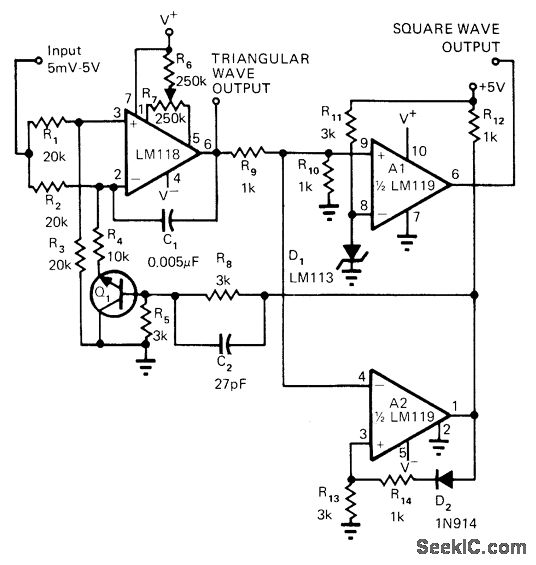
SQUARE TRIANGLE VCO
This circuit utilizes a DC control voltage ranging from 5 mV to 5 V to regulate the frequency of both square and triangle wave outputs, exhibiting good linearity. The peak value of the triangle output is accurately established at 2.44...

1.5 Watt FM Transmitter circuit
This project was completed successfully, achieving the desired frequency and strength. For assistance, please reach out for support in resolving any issues.
The project involves the design and implementation of an electronic circuit that operates at a specified frequency and strength,...

Single Chip Stereo FM Transmitter Circuit
An FM modulator that modulates a carrier frequency with the composite signal, and an RF amplifier that provides enough power to be transmitted through an antenna. Here is the schematic diagram of the FM transmitter circuit: The core of this...

FM
A wireless FM transmitter, commonly referred to as an FM transmitter, utilizes two transistors, specifically the 2N2222 model. When in operation, this FM transmitter requires a voltage supply from a 9-volt battery and utilizes an antenna with a length of...

pen transmitter
This spy pen FM transmitter circuit can be built into a ballpoint pen. It is crystal-controlled.
The spy pen FM transmitter circuit is designed to be compact and discreet, allowing for covert audio transmission. The circuit utilizes a crystal oscillator to...

long range fm transmitter circuit
The transmitter described here includes an additional RF power amplifier stage following the oscillator stage, which increases the output power to 200-250 milliwatts. When connected to a properly matched 50-ohm ground plane antenna or a multi-element Yagi antenna, this transmitter...

Low-Power Metronome
This metronome operates on a current of only 0.25 mA, making it suitable for battery-powered applications. It offers a tempo range from 34 to 246 beats per minute. The circuit can utilize a CMOS timer, such as the LM555 CN...

Stereo FM transmitter using BA1404
A high-quality stereo FM transmitter circuit is presented. This circuit utilizes the BA1404 integrated circuit from ROHM Semiconductors. The BA1404 is a monolithic FM stereo modulator that incorporates a stereo modulator, FM modulator, and RF amplifier circuitry. The FM modulator...