


fmradio
#FM radio
#SONY 1619
#AM/FM
#USB power
#double sided PTH board
#antenna
#speaker
#battery option
#PC compatible
#radio IC

Description: The FM radio project described here is based on the SONY 1619 chip. This is a single-chip radio, meaning that all functions from the antenna to the speaker are managed by the Sony integrated circuit, which is specifically designed for AM/FM radios. The radio is constructed on a double-sided plated through-hole (PTH) board and operates using USB power. There is an option to add a 6V battery (using 4xAA or AAA batteries), although this is not included in the kit. USB power is chosen because most users have access to a USB port on their PCs. Since the SONY 1619 is a compact chip with closely spaced pins for soldering, there will be an option to purchase kits with a pre-soldered chip at no additional cost.
The FM radio project utilizes the SONY 1619 integrated circuit, which is engineered for efficient AM and FM radio reception. This single-chip solution simplifies the design by integrating all necessary components, including the antenna interface, demodulator, audio amplifier, and speaker output, into one compact package. The use of a double-sided PTH board enhances the circuit's reliability and allows for a more organized layout, minimizing interference and optimizing performance.
Powering the device via USB provides convenience and compatibility, as most users have easy access to USB ports on computers or power adapters. The inclusion of a battery option allows for portability, enabling the radio to be used in locations without immediate access to power sources. The choice of 4xAA or AAA batteries offers flexibility in power supply, catering to user preferences for battery type.
For assembly, the close pin configuration of the SONY 1619 chip may pose challenges for manual soldering. To address this, the project offers a pre-soldered chip option, facilitating easier assembly for those less experienced in soldering techniques. This option is provided at no extra cost, making the project accessible to a wider audience.
The schematic design of the FM radio includes essential components such as capacitors for filtering, resistors for biasing, and connectors for the speaker and power supply. The layout is optimized for signal integrity, ensuring clear audio output while minimizing noise interference. Overall, this FM radio project represents a practical application of integrated circuit technology in consumer electronics, providing an engaging experience for both hobbyists and electronics enthusiasts.FM Radio project detailed here is based on SONY 1619 chip. This is single chip radio means, everything from Antenna to Speaker is done by Sony IC, specially designed for AM/FM Radios. Radio is designed on a double sided PTH Board and works on USB power. There is an option to add 6V battery (4xAA or AAA) but that is not part of the kit. USB power is selected in a view that most of us have a PC and one USB port is available for this radio. Since Sony 1619 is a very compact chip with very close pins to solder, we will offer an option to get kits with pre-soldered chip if you like that way. (at no extra cost)
The FM radio project utilizes the SONY 1619 integrated circuit, which is engineered for efficient AM and FM radio reception. This single-chip solution simplifies the design by integrating all necessary components, including the antenna interface, demodulator, audio amplifier, and speaker output, into one compact package. The use of a double-sided PTH board enhances the circuit's reliability and allows for a more organized layout, minimizing interference and optimizing performance.
Powering the device via USB provides convenience and compatibility, as most users have easy access to USB ports on computers or power adapters. The inclusion of a battery option allows for portability, enabling the radio to be used in locations without immediate access to power sources. The choice of 4xAA or AAA batteries offers flexibility in power supply, catering to user preferences for battery type.
For assembly, the close pin configuration of the SONY 1619 chip may pose challenges for manual soldering. To address this, the project offers a pre-soldered chip option, facilitating easier assembly for those less experienced in soldering techniques. This option is provided at no extra cost, making the project accessible to a wider audience.
The schematic design of the FM radio includes essential components such as capacitors for filtering, resistors for biasing, and connectors for the speaker and power supply. The layout is optimized for signal integrity, ensuring clear audio output while minimizing noise interference. Overall, this FM radio project represents a practical application of integrated circuit technology in consumer electronics, providing an engaging experience for both hobbyists and electronics enthusiasts.FM Radio project detailed here is based on SONY 1619 chip. This is single chip radio means, everything from Antenna to Speaker is done by Sony IC, specially designed for AM/FM Radios. Radio is designed on a double sided PTH Board and works on USB power. There is an option to add 6V battery (4xAA or AAA) but that is not part of the kit. USB power is selected in a view that most of us have a PC and one USB port is available for this radio. Since Sony 1619 is a very compact chip with very close pins to solder, we will offer an option to get kits with pre-soldered chip if you like that way. (at no extra cost)

Antenna Combiner
The Antenna Combiner (A3021) is an active combiner designed to accommodate four 50-ohm coaxial antenna connections. It combines the signals from these four inputs, resulting in a net gain of approximately +11 dB. The A3021 is specifically intended for use...

Ground pole & 2-Half-Wave Dipole Antenna
This Antenna is most widely used all over the world. For example, when you see a police car it has a transmitter with Ground Pole Antenna. The body of the car serves as ground. It accepts load from a 50-ohm...

Bi-Level Squelch
The proper operation of the squelch circuit in any FM radio is essential to avoid listening to discriminator noise. This is particularly critical in a repeater system. The primary function of a squelch circuit is to detect the presence of...

Single Chip FM Radio Circuit with Diagram using TDA 7000 IC
A simple FM radio circuit with a diagram and schematic using the IC TDA 7000. This low-cost single-chip FM radio circuit design is easy to assemble and is suitable for creating a portable FM radio.
The FM radio circuit utilizing the...

A simple three-way speaker crossover circuit diagram
The divider acts as the speaker's brain and is crucial for sound quality. The music amplifier's output signal must be processed through a wave filter element to divide it into specific frequency signals for each unit. A scientifically and rationally...

Antennas for HAM transmitters
Antenna is the means by which a wireless operator puts his signal into the space and also through which he picks up the signals of the stations with which he wants to communicate. Hence after having a good Receiver and...

speaker to microphone circuit converter
This circuit diagram illustrates the conversion of a speaker into a microphone. When sound waves impact the diaphragm of a speaker, fluctuations occur in the coil, generating an induced voltage. This induced voltage is typically substantial but low in output....
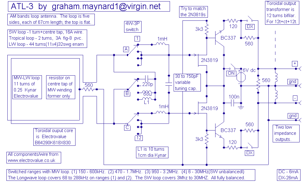
ATL-3 Loop Antenna
This antenna is the result of long term development and user feedback. All ATL-3 loop windings are centre tapped and balanced w.r.t. their amplifier/receiver chassis ground, and therefore electric field interference pick up tends to self cancel. Magnetic noise fields,...

USB powered device with multiple Decoupling Capacitors
A USB powered device with multiple integrated circuits (ICs). It is standard practice to use a combination of various range capacitors for decoupling each individual IC, with the smallest capacitors placed as close as possible to the ICs and larger...