


Goodman Band Imaging Receiver

Description: By utilizing specific characteristics of superheterodyne action that are not typically exploited, it is feasible to cover both the 80-meter and 40-meter amateur radio bands with a single pair of coils, in addition to frequencies where commercial point-to-point continuous wave (CW) and shortwave broadcast signals can be received. Minimizing reception at the image frequency is crucial for the practical application of the superheterodyne principle, unless the image frequency falls within another amateur band that is desired for reception. This discussion delves into the band-imaging receiver topology that gained popularity in the 1950s, as introduced by Don Mix, W1TS, and Byron Goodman, W1DX. This design approach employs a single local oscillator tuning span to receive two bands, where each band is the image of the other, without requiring oscillator-tank switching.
In a basic regenerative detector behind a mixer receiver with a 1.6 MHz intermediate frequency (IF), the same plug-in oscillator coil is utilized to tune the ranges of 5.4 to 10.0 MHz and 9.5 to 14.5 MHz. The oscillator coil is positioned on the low-frequency side of the signal for the higher range. This configuration not only eliminates the need for a second coil but also enhances stability at the higher frequency range. The receiver will respond to signals either 1600 kHz higher or lower than the oscillator frequency, with the unwanted response or image being filtered out by the tuning of the radio frequency (RF) circuit.
On the three lower-frequency ranges, it is possible to find two tuning spots on the variable capacitor (C1) where incoming random noise peaks. The lower-frequency peak, which requires the highest tuning capacity at C1, is the correct one, as the oscillator frequency is 1600 kHz higher than the incoming signal. Conversely, on the fourth range, the oscillator is tuned 1600 kHz lower than the incoming signal. The specific side used does not significantly impact performance, aside from calibration considerations.
The Mix-Goodman receiver concept was notably detailed in the March 1950 issue of QST, in the article "A Beginner's Four-Tube Superhet Receiver" by Don Mix, W1TS. This design aimed to minimize the cost of a first-time amateur radio station by providing coverage of two bands simultaneously (primarily 80 meters [3.5 to 4.0 MHz] and 40 meters [7.0 to 7.3 MHz]), with the potential for adding coverage of the 20-meter [14 MHz] band as an option. Unlike Grammer's simpler receiver, Mix's circuit fundamentally incorporates band imaging, allowing the receiver to cover its two main signal-frequency ranges using a single local oscillator tuning span (5.0 to 5.8 MHz). This configuration converts both bands to a relatively high 1.5 MHz IF, enabling the selection of either LO-IF or LO+IF through straightforward signal-frequency filtering.
The innovative aspect of Mix's design is that it organizes the coverage of the two bands in a sequential manner on the tuning dial, with 4.0 MHz on the 80-meter band (LO at 5.5 MHz) corresponding to 7.0 MHz on the 40-meter band. Only a retuning of the RF-input grid of the 6SB7Y converter is required to switch between the two bands. The arrangement allows for the tuning of the 80-meter amateur radio band (3500 to 4000 kHz) and the 40-meter amateur radio band (7000 to 7300 kHz) using a single 800 kHz-wide local oscillator tuning range (5000 to 5800 kHz). While this setup may seem to waste revolutions of the tuning dial on non-amateur frequencies, it effectively maximizes the use of the available tuning range for amateur radio applications.By taking advantage of certain characteristics of superhet action not normally used, it is possible with one pair of coils to cover both the 80- and 40-meter ham bands as well as ranges where commercial point-to-point c. w. and shortwave broadcast signals may be found. ”Donald H. Mix, W1TS, "A Beginner`s Four-Tube Superhet Receiver, " QST, March 19 50 CE Minimizing reception at the image frequency is fundamental to useful practical application of the superheterodyne principle ”unless the image happens to lie in another amateur radio band, and you want to receive it. This page explores the band-imaging receiver topology popularized in the 1950s by Don Mix, W1TS, and Byron Goodman, W1DX ”a design approach that uses a single local-oscillator tuning span to receive either of two bands without oscillator-tank switching, each band the image of the other.
We see its pre-echo in George Grammer, "A Two-Tube Superhet, " QST, February 1941 CE, pages 12 15 and 92: In a simple regenerative-detector-behind-a-mixer receiver with a 1. 6-MHz intermediate frequency (IF), the same plug-in oscillator coil is used to tune the ranges 5. 4 10. 0 and 9. 5 14. 5 MHz. Wrote Grammer: It will be noted that the same oscillator coil, D, is used for two frequency ranges. This is possible because the oscillator signal is placed on the low-frequency side of the signal on the higher range.
This not only avoids winding a second coil, but also gives somewhat greater stability at the highest-frequency range. . . . A word about images. The receiver will, of course, respond to signals either 1600 kc. higher or 1600 kc. lower than the oscillator frequency. The unwanted response, or image, is discriminated against by the tuning of the r. f. circuit. On the three lower-frequency ranges, when it is possible to find two tuning spots on C1 at which incoming random noise peaks up, the lower-frequency peak (the one requiring the highest tuning capacity at C1) is the right one.
The oscillator frequency is 1600 kc. higher than that of the incoming signal on these three ranges. On the fourth range the reverse is true, since here the oscillator is tuned 1600 kc. lower. Actually, it does not matter a great deal which side is used except for calibration purposes. The two-bands-for-the-price-of-one story of the Mix-Goodman receiver begins in earnest with the publication in March 1950 CE QST of "A Beginner`s Four-Tube Superhet Receiver, " by Don Mix, W1TS. Designed to keep the cost of a first-time amateur radio station down, Mix`s receiver provided coverage of two bands at a time (principally, 80 meters [3.
5 to 4. 0 MHz] and 40 meters [7. 0 to 7. 3 MHz], although coverage of the 20-meter [14-MHz] band could also be installed, and may have been added as an afterthought) without switching or unplugging any frequency-determining components. Unlike Grammer`s simple receiver, Mix`s circuit uses band-imaging as a fundamental feature: The receiver covers its two principal signal-frequency ranges with one local-oscillator (LO) tuning span (5.
0 5. 8 MHz), which converts both bands to a relatively high (1. 5-MHz) IF to allow selection of LO ’IF or LO+IF with simple signal-frequency filtering, one range the image of the other. The novelty of Mix`s implementation is that coverage of the two bands is arranged end-to-beginning on the tuning dial, with 4.
0 MHz on the 80-meter band (LO, 5. 5 MHz) corresponding to 7. 0 MHz on the 40-meter band (Figure 1). Only retuning the RF-input grid of the 6SB7Y converter is necessary to change from one band to the other. Figure 1 ”Don Mix`s band-imaging arrangement tunes the 80-meter amateur radio band (3500 to 4000 kHz, orange) and the 40-meter amateur radio band (7000 to 7300 kHz, blue) with a single 800-kHz-wide local-oscillator tuning range (5000 to 5800 kHz).
Arranging the bands end to end seemingly wastes revolutions of the set`s 6:1-reduction tuning dial on non-amateur frequencies: 4. 0
In a basic regenerative detector behind a mixer receiver with a 1.6 MHz intermediate frequency (IF), the same plug-in oscillator coil is utilized to tune the ranges of 5.4 to 10.0 MHz and 9.5 to 14.5 MHz. The oscillator coil is positioned on the low-frequency side of the signal for the higher range. This configuration not only eliminates the need for a second coil but also enhances stability at the higher frequency range. The receiver will respond to signals either 1600 kHz higher or lower than the oscillator frequency, with the unwanted response or image being filtered out by the tuning of the radio frequency (RF) circuit.
On the three lower-frequency ranges, it is possible to find two tuning spots on the variable capacitor (C1) where incoming random noise peaks. The lower-frequency peak, which requires the highest tuning capacity at C1, is the correct one, as the oscillator frequency is 1600 kHz higher than the incoming signal. Conversely, on the fourth range, the oscillator is tuned 1600 kHz lower than the incoming signal. The specific side used does not significantly impact performance, aside from calibration considerations.
The Mix-Goodman receiver concept was notably detailed in the March 1950 issue of QST, in the article "A Beginner's Four-Tube Superhet Receiver" by Don Mix, W1TS. This design aimed to minimize the cost of a first-time amateur radio station by providing coverage of two bands simultaneously (primarily 80 meters [3.5 to 4.0 MHz] and 40 meters [7.0 to 7.3 MHz]), with the potential for adding coverage of the 20-meter [14 MHz] band as an option. Unlike Grammer's simpler receiver, Mix's circuit fundamentally incorporates band imaging, allowing the receiver to cover its two main signal-frequency ranges using a single local oscillator tuning span (5.0 to 5.8 MHz). This configuration converts both bands to a relatively high 1.5 MHz IF, enabling the selection of either LO-IF or LO+IF through straightforward signal-frequency filtering.
The innovative aspect of Mix's design is that it organizes the coverage of the two bands in a sequential manner on the tuning dial, with 4.0 MHz on the 80-meter band (LO at 5.5 MHz) corresponding to 7.0 MHz on the 40-meter band. Only a retuning of the RF-input grid of the 6SB7Y converter is required to switch between the two bands. The arrangement allows for the tuning of the 80-meter amateur radio band (3500 to 4000 kHz) and the 40-meter amateur radio band (7000 to 7300 kHz) using a single 800 kHz-wide local oscillator tuning range (5000 to 5800 kHz). While this setup may seem to waste revolutions of the tuning dial on non-amateur frequencies, it effectively maximizes the use of the available tuning range for amateur radio applications.By taking advantage of certain characteristics of superhet action not normally used, it is possible with one pair of coils to cover both the 80- and 40-meter ham bands as well as ranges where commercial point-to-point c. w. and shortwave broadcast signals may be found. ”Donald H. Mix, W1TS, "A Beginner`s Four-Tube Superhet Receiver, " QST, March 19 50 CE Minimizing reception at the image frequency is fundamental to useful practical application of the superheterodyne principle ”unless the image happens to lie in another amateur radio band, and you want to receive it. This page explores the band-imaging receiver topology popularized in the 1950s by Don Mix, W1TS, and Byron Goodman, W1DX ”a design approach that uses a single local-oscillator tuning span to receive either of two bands without oscillator-tank switching, each band the image of the other.
We see its pre-echo in George Grammer, "A Two-Tube Superhet, " QST, February 1941 CE, pages 12 15 and 92: In a simple regenerative-detector-behind-a-mixer receiver with a 1. 6-MHz intermediate frequency (IF), the same plug-in oscillator coil is used to tune the ranges 5. 4 10. 0 and 9. 5 14. 5 MHz. Wrote Grammer: It will be noted that the same oscillator coil, D, is used for two frequency ranges. This is possible because the oscillator signal is placed on the low-frequency side of the signal on the higher range.
This not only avoids winding a second coil, but also gives somewhat greater stability at the highest-frequency range. . . . A word about images. The receiver will, of course, respond to signals either 1600 kc. higher or 1600 kc. lower than the oscillator frequency. The unwanted response, or image, is discriminated against by the tuning of the r. f. circuit. On the three lower-frequency ranges, when it is possible to find two tuning spots on C1 at which incoming random noise peaks up, the lower-frequency peak (the one requiring the highest tuning capacity at C1) is the right one.
The oscillator frequency is 1600 kc. higher than that of the incoming signal on these three ranges. On the fourth range the reverse is true, since here the oscillator is tuned 1600 kc. lower. Actually, it does not matter a great deal which side is used except for calibration purposes. The two-bands-for-the-price-of-one story of the Mix-Goodman receiver begins in earnest with the publication in March 1950 CE QST of "A Beginner`s Four-Tube Superhet Receiver, " by Don Mix, W1TS. Designed to keep the cost of a first-time amateur radio station down, Mix`s receiver provided coverage of two bands at a time (principally, 80 meters [3.
5 to 4. 0 MHz] and 40 meters [7. 0 to 7. 3 MHz], although coverage of the 20-meter [14-MHz] band could also be installed, and may have been added as an afterthought) without switching or unplugging any frequency-determining components. Unlike Grammer`s simple receiver, Mix`s circuit uses band-imaging as a fundamental feature: The receiver covers its two principal signal-frequency ranges with one local-oscillator (LO) tuning span (5.
0 5. 8 MHz), which converts both bands to a relatively high (1. 5-MHz) IF to allow selection of LO ’IF or LO+IF with simple signal-frequency filtering, one range the image of the other. The novelty of Mix`s implementation is that coverage of the two bands is arranged end-to-beginning on the tuning dial, with 4.
0 MHz on the 80-meter band (LO, 5. 5 MHz) corresponding to 7. 0 MHz on the 40-meter band (Figure 1). Only retuning the RF-input grid of the 6SB7Y converter is necessary to change from one band to the other. Figure 1 ”Don Mix`s band-imaging arrangement tunes the 80-meter amateur radio band (3500 to 4000 kHz, orange) and the 40-meter amateur radio band (7000 to 7300 kHz, blue) with a single 800-kHz-wide local-oscillator tuning range (5000 to 5800 kHz).
Arranging the bands end to end seemingly wastes revolutions of the set`s 6:1-reduction tuning dial on non-amateur frequencies: 4. 0

rf modem robotics project using pic16f84 microcontroller
RF technology is an exciting field to incorporate into electronic designs. However, for beginners, constructing reliable RF transmitters and receivers can be challenging.
RF (Radio Frequency) technology plays a crucial role in modern communication systems, enabling wireless data transmission over various...

GBPPR 1 GHz RF Spectrum Analyzer
An RF spectrum analyzer is an essential tool for experimenters. The spectrum analyzer project described here is an enhancement of the "Spectrum Analyzer for the Radio Amateur" (Part 2) project by Wes Hayward (W7ZOI) and Terry White (K7TAU), which appeared...

Jammer circuit
The frequency jammer operates by generating interfering RF noise centered around a 2.45 GHz carrier frequency. As the power of this noise increases, the signal-to-noise ratio of the wireless communication channel decreases, leading to a higher bit error rate until...

Tuned radio frequency receiver
A tuned radio frequency (TRF) receiver is a radio receiver typically consisting of multiple tuned radio frequency amplifiers followed by circuits for detecting and amplifying the audio signal. A three-stage TRF receiver includes an RF stage, a detector stage, and...

RF Dummy load
The load described here is capable of handling up to 10 watts of RF power for a couple of minutes and is designed for the widely used 50 ohms impedance. It consists of ten parallel connected 560 ohms 1 watt...
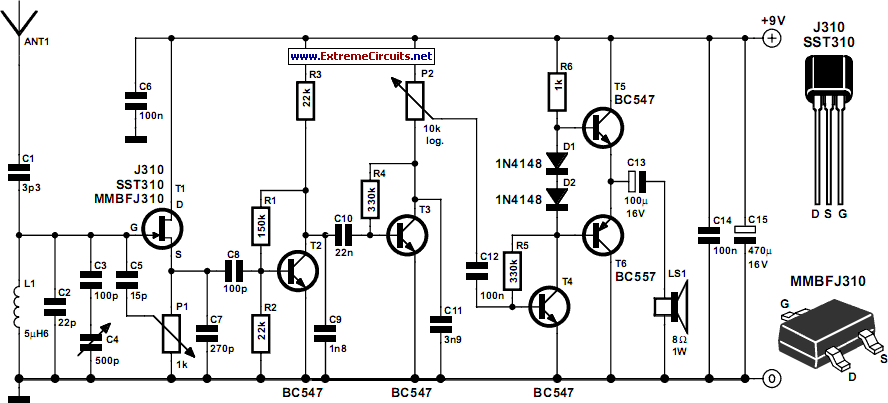
Tuned Radio Frequency (TRF) Receiver
Superheterodyne receivers have been mass-produced since around 1924, but for reasons of cost did not become successful until the 1930s.
Superheterodyne receivers represent a pivotal advancement in radio technology, characterized by their ability to convert high-frequency signals into lower intermediate...

Reflex Radio Receiver
The RF signal is transmitted from the antenna through CI to a tuned circuit consisting of LI and C2. One end of L2 delivers the RF signal to the base of Q1 for amplification, while the other end connects to...
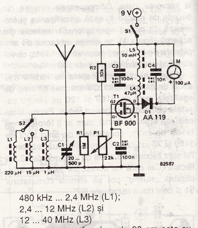
Radio Field Indicator Circuit
An RF field indicator is needed to verify power stages and transmitter antennas. This radio field indicator allows for the measurement of radiated energy from antennas.
An RF field indicator is a crucial device in the field of telecommunications and broadcasting....

3-Wire Receiver/Message Demuxer
This 3-wire receiver verifies the initial four data bits of 16 received bits against a predetermined address. If the two match, the remaining 12 bits are stored in two 6-bit flip-flop registers. The design can utilize either CMOS or TTL...