


Hum Reducer For Direct-Conversion Receivers Circuit
#hum reducer
#direct-conversion receivers
#power line hum
#ripple reduction
#regulated power supply
#filtering
#balancing choke
#RF circuits
#leakage current

Description: One solution for AC power line hum and ripple, which is caused by leakage current, is to utilize a well-regulated and filtered 9 to 18 VDC power supply that incorporates a balancing choke (Tl in this illustration) between the power supply and the DCR.
A well-regulated and filtered DC power supply is critical in minimizing the effects of AC power line hum and ripple, which can adversely affect the performance of sensitive electronic circuits. The voltage range of 9 to 18 VDC is commonly used in various applications, making this solution versatile.
The incorporation of a balancing choke serves to further mitigate the undesirable effects of leakage current. A balancing choke, also known as a common-mode choke, is designed to suppress high-frequency noise and ripple by providing impedance to differential and common-mode signals. This component is placed in series with the power supply output, effectively filtering out unwanted AC components while allowing the desired DC voltage to pass through.
In a typical schematic, the power supply output connects to the input of the balancing choke, which is then connected to the Direct Current Resistance (DCR) load. The choke consists of two coils wound on a magnetic core, which helps in creating a magnetic field that opposes the noise currents, thus improving the overall power quality delivered to the load.
The design of the power supply should also include adequate filtering capacitors to smooth out any residual ripple voltage. These capacitors should be rated for the appropriate voltage and capacitance values to ensure effective filtering. Additionally, the power supply circuitry may incorporate voltage regulation components, such as linear regulators or switching regulators, to maintain a stable output voltage within the specified range, regardless of variations in the input voltage or load conditions.
In summary, utilizing a well-regulated and filtered 9 to 18 VDC power supply with a balancing choke effectively addresses the issues of AC power line hum and ripple, ensuring stable and clean power delivery to sensitive electronic devices. One cure for ac power line hum and ripple (caused by leakage current) is to use a well-reg-ulated and filtered 9- to 18-Vdc power supply with a balancing choke (Tl in this illustration) between the power supply and the DCR.
A well-regulated and filtered DC power supply is critical in minimizing the effects of AC power line hum and ripple, which can adversely affect the performance of sensitive electronic circuits. The voltage range of 9 to 18 VDC is commonly used in various applications, making this solution versatile.
The incorporation of a balancing choke serves to further mitigate the undesirable effects of leakage current. A balancing choke, also known as a common-mode choke, is designed to suppress high-frequency noise and ripple by providing impedance to differential and common-mode signals. This component is placed in series with the power supply output, effectively filtering out unwanted AC components while allowing the desired DC voltage to pass through.
In a typical schematic, the power supply output connects to the input of the balancing choke, which is then connected to the Direct Current Resistance (DCR) load. The choke consists of two coils wound on a magnetic core, which helps in creating a magnetic field that opposes the noise currents, thus improving the overall power quality delivered to the load.
The design of the power supply should also include adequate filtering capacitors to smooth out any residual ripple voltage. These capacitors should be rated for the appropriate voltage and capacitance values to ensure effective filtering. Additionally, the power supply circuitry may incorporate voltage regulation components, such as linear regulators or switching regulators, to maintain a stable output voltage within the specified range, regardless of variations in the input voltage or load conditions.
In summary, utilizing a well-regulated and filtered 9 to 18 VDC power supply with a balancing choke effectively addresses the issues of AC power line hum and ripple, ensuring stable and clean power delivery to sensitive electronic devices. One cure for ac power line hum and ripple (caused by leakage current) is to use a well-reg-ulated and filtered 9- to 18-Vdc power supply with a balancing choke (Tl in this illustration) between the power supply and the DCR.

power supply (300V, 50mA + 6.3V, 3A max)
This regulated power supply was built as a simplified outboard version of a PSU in my first phono stage. Replacing hexfreds with tube rectifier eliminates the need for power-on sequencing. Chassis (salvaged from a hospital laser PSU) size is 180W*240D*100H...

Self switching Power Supply
One of the main features of the regulated power supply circuit being presented is that though fixed-voltage regulator LM7805 is used in the circuit, its output voltage is variable. This is achieved by connecting a potentiometer between common terminal of...

3-24V / 3A power supply
This regulated power supply can be adjusted from 3 to 25 volts and is current limited to 2 amps as shown, but may be increased to 3 amps or more by selecting a smaller current sense resistor (0.3 ohm). The...
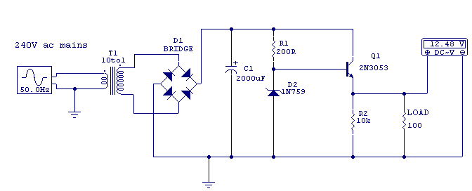
Regulated 12 Volt Supply
This circuit above uses a 13 volt zener diode, D2 which provides the voltage regulation. Approximately 0.7 Volts are dropped across the transistors b-e junction, leaving a higher current 12.3 Volt output supply. This circuit can supply loads of up...

13.8Vdc 2A Regulated Power Supply Circuit
This regulated power supply consists of a step-down transformer T1, a full-wave rectifier bridge (D1 through D4), and a filtering regulator circuit made up of C1, C2, R1, R2, R8, D5, and Q1. When 120 Vac is provided, the neon-lamp...
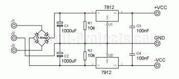
Dual Regulated Power Supply
A center tap transformer is required. For instance, to obtain a 12V output, connect J1 to the 15V transformer output, J2 to 0V, and J3 to another 15V.
A center tap transformer is a specialized transformer that has a secondary winding...
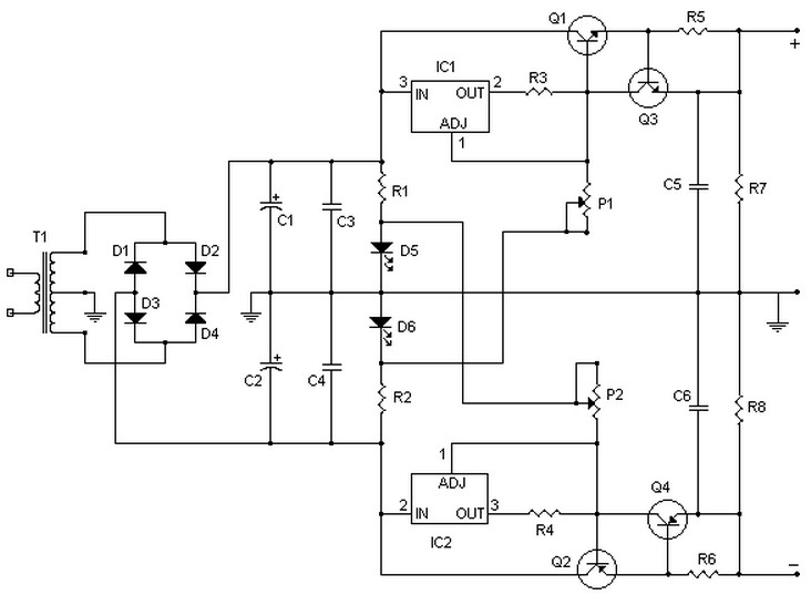
symmetrical regulated power supply and variable 0 to 30v 2a
This circuit can deliver up to 15V per section (-15V and +15V), or up to 30V as a whole, for a maximum consumption of 2A. With modifications, it could be adjusted to provide up to 5A or more. Transistors Q1...

-15-V-1-a-regulated-power-supply
The supply receives -20 V from the rectifier/filter, which is connected to the collector of the Darlington PNP pass transistor, a TIP105. The base drive for the TIP105 is provided through resistor R5. The base of the TIP105 is activated...
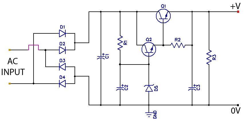
low ripple regulated power supply
The value of capacitor C2 can be selected to achieve the desired level of smoothness, as its capacitance is effectively amplified by the combined gains of transistors Q1 and Q2. For instance, if a capacitance of 100 µF is selected...