


la1800 portable am fm radio circuit
#LA1800
#AM radio
#FM radio
#portable radio
#Sanyo Semiconductors
#earphone speakers
#radio circuit
#IC circuit

Description: This portable AM/FM radio circuit is designed using the LA1800 integrated circuit (IC) along with several external components. The LA1800, manufactured by Sanyo Semiconductors, requires only a few additional components for its operation. The output signal is directed to earphone speakers; however, an additional speaker can be connected, which necessitates the inclusion of a small power audio amplifier.
The portable AM/FM radio circuit utilizing the LA1800 IC is a compact and efficient design suitable for personal audio applications. The LA1800 is a highly integrated radio receiver IC that simplifies the design process by incorporating essential functions such as frequency selection, demodulation, and audio amplification within a single package.
The circuit typically includes a few passive components, such as resistors and capacitors, which are used to set the gain and filter the audio output. An antenna is also required for signal reception, which can be a simple wire or a more sophisticated telescopic antenna, depending on the desired range and reception quality.
For the output stage, the circuit is designed to drive earphone speakers directly. In scenarios where higher audio output is necessary, an external small power audio amplifier can be added. This amplifier should be compatible with the output level of the LA1800 to prevent distortion and ensure optimal performance. The connection to the amplifier usually involves routing the audio output from the LA1800 to the input of the amplifier, which then drives the larger speaker.
Overall, this circuit design is ideal for hobbyists and engineers looking to create a portable radio solution with minimal components while maintaining high audio quality and functionality.This portable am fm radio circuit is designed using the LA1800 IC and some other external components. As you can see in this circuit diagram the LA1800 manufactured by Sanyo Semiconductors, require few additional components.
Also the output signal is driven into earphone speakers, but you can use an additional speaker ( in that case you need t o connect an additional small power audio amplifier ).
The portable AM/FM radio circuit utilizing the LA1800 IC is a compact and efficient design suitable for personal audio applications. The LA1800 is a highly integrated radio receiver IC that simplifies the design process by incorporating essential functions such as frequency selection, demodulation, and audio amplification within a single package.
The circuit typically includes a few passive components, such as resistors and capacitors, which are used to set the gain and filter the audio output. An antenna is also required for signal reception, which can be a simple wire or a more sophisticated telescopic antenna, depending on the desired range and reception quality.
For the output stage, the circuit is designed to drive earphone speakers directly. In scenarios where higher audio output is necessary, an external small power audio amplifier can be added. This amplifier should be compatible with the output level of the LA1800 to prevent distortion and ensure optimal performance. The connection to the amplifier usually involves routing the audio output from the LA1800 to the input of the amplifier, which then drives the larger speaker.
Overall, this circuit design is ideal for hobbyists and engineers looking to create a portable radio solution with minimal components while maintaining high audio quality and functionality.This portable am fm radio circuit is designed using the LA1800 IC and some other external components. As you can see in this circuit diagram the LA1800 manufactured by Sanyo Semiconductors, require few additional components.
Also the output signal is driven into earphone speakers, but you can use an additional speaker ( in that case you need t o connect an additional small power audio amplifier ).

Simple AM radio
This is a straightforward AM radio circuit utilizing only two transistors. The coil L1 and variable capacitor C1 create the tank circuit. Transistor Q1 is responsible for demodulation, and the demodulated signal is accessible at the base of Q1. This...

TEA5764UK TEA5764UK FM Radio + RDS
The TK10931V is an intermediate frequency (IF) integrated circuit that incorporates two IF systems—one designated for frequency modulation (FM) and the other for amplitude modulation (AM)—along with a detector. This device is suitable for use in amateur radios, CB radios,...

One Transistor FM Radio With Improved Audio Gain
The following circuit presents a schematic diagram for a one-transistor FM radio with enhanced audio gain. Features include a super-regenerative design.
The one-transistor FM radio circuit utilizes a super-regenerative architecture, which is known for its simplicity and efficiency in receiving FM...

mk484 am radio circuit design project
The MK484 AM radio circuit offers a comprehensive solution featuring an RF amplifier, detection, and an automatic gain control (AGC) circuit. It requires only a few external components to achieve high-quality AM tuning. The circuit has an input impedance of...

PC FM radio
Stabilised tendency of catering: Vcc=9~12V. Frequency of reception: 88~108MHz. Consumption: 100mA. If you know some language of programming as C++, PASCAL, VISUAL BASIC, DELPHI etc you can write a program which will send in the parallel door (378 I) of...

FM radio tuning circuit circuit
The FM radio circuit consists of a high-frequency amplifier (VT1), a mixer and local oscillator (VT2), and additional components. The circuit includes an FM radio antenna for signal detection, with an input transformer (L1) connected to a gate transistor (VT1),...
MOSFET-BASED PREAMPLIFIER FOR FM RADIO Project PCB
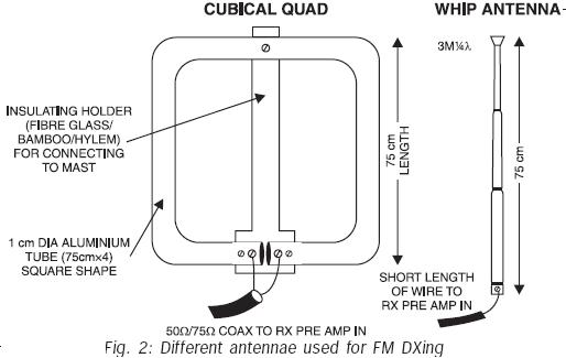
FM transmissions can be received within a range of 40 km. In fringe areas, the signal may be very weak. FM DXing refers to the practice of receiving distant stations (1500 km or more) on the FM band (88-108 MHz)....

Active AM Radio Antenna Amplifier / Preamplifier Circuit
The antenna amplifier circuit comprises approximately 40 components, featuring two NPN transistors (BC548), one MOSFET (BF981), two varicap diodes (KV1235), and a 6.2V zener diode. It includes a 330µH inductor/coil, which can be modified for operation on different frequency bands....

AM Radio Receiver Circuit With BF959 Transistor
Function: step down the antenna impedance from high to 50 ohms and not, as would be expected, to effect a change from balanced to unbalanced. Component: ..
In the context of antenna systems, impedance matching is crucial for maximizing power transfer...