


make this one transistor radio receiver
#radio receiver
#single transistor
#simple circuit
#AM radio
#DIY radio
#RF circuits
#wireless communication
#homebrew radio
#minimalist design
#analog circuits

Description: This is likely the simplest radio that can be assembled. The circuit design is straightforward enough to be completed in just a few minutes, allowing users to listen to their favorite programs immediately. The circuit of a single transistor radio, although appearing ordinary, includes all necessary stages for receiving radio stations. However, this simplicity comes with certain limitations; the design is capable of receiving only strong signals, and selectivity may be poor, especially when multiple strong stations are present on the same band. The diagram below illustrates how to construct the single transistor radio, which primarily relies on one transistor as the main active component. The weak but concentrated signal from the LC tuned stage is fed into the base of the transistor, which functions as both a demodulator and an amplifier. A coupling capacitor at the base ensures that only the radio signal reaches the transistor while blocking the DC component from the power supply. Inserting headphones activates the circuit, which operates until the headphones are removed, eliminating the need for an external switch and resulting in a compact design.
The single transistor radio circuit operates on the principle of amplitude modulation (AM) reception, utilizing a minimalistic design that emphasizes efficiency and ease of assembly. The core component, a single transistor, serves dual purposes: it amplifies the weak audio signals received from the antenna and demodulates the amplitude-modulated signals to extract audio information.
The radio circuit typically begins with an LC (inductor-capacitor) tuned circuit, which is responsible for selecting the desired frequency from the radio spectrum. This tuned circuit is designed to resonate at the frequency of the desired radio station, allowing it to filter out other frequencies. The output of the LC circuit is a weak signal that is then coupled to the base of the transistor through a coupling capacitor. This capacitor is critical as it blocks any DC voltage present, allowing only the AC audio signal to pass through to the transistor.
Once the signal reaches the transistor's base, it is amplified. The transistor operates in its active region, where even small changes in base current result in significant changes in collector current, thereby amplifying the audio signal. The amplified output can then be fed to headphones or a speaker, allowing the user to hear the broadcast.
The design also features a unique automatic switch mechanism facilitated by the headphone jack. When headphones are plugged in, the circuit is completed, allowing current to flow and the radio to function. Removing the headphones interrupts the circuit, effectively turning off the radio. This design choice enhances the compactness and user-friendliness of the radio, as it eliminates the need for additional components such as external switches.
Overall, the single transistor radio exemplifies a balance between simplicity and functionality, making it an ideal project for beginners in electronics. Despite its limitations in selectivity and sensitivity, it provides an excellent introduction to radio technology and circuit design principles.This is probably the simplest radio that one could ever imagine of making. The circuit is so simple that it could be finished assembling within a few minutes and you are already listening your favorite programs over it. The circuit of a single transistor radio shown here though looks pretty ordinary, incorporates all the above stages and thus
becomes just suitable for receiving the radio stations. However simplicity will always involve some drawbacks also, here the present design will be capable of receiving only strong stations and also selectivity might not be very pleasing, typically if there are a couple of strong stations mingling around the band. The figure below shows how the single transistor radio can be made, we can clearly see that it just involves a single transistor as the main active component.
The concentrated but very low in power signal from the above LC tuned stage is fed to the base of the transistor which as performs the function of a demodulator as well as a amplifier stage. The coupling capacitor at the base of the transistor makes sure only the radio information passes to the transistor while the DC component from the supply is appropriately blocked.
Plugging in the headphone initiates the circuit and the circuit starts operating with its functions and the switches OFF itself when the headphone is removed from the circuit. This eliminates the need of an external switch to be associated with the circuit, making the unit very compact.
The single transistor radio circuit operates on the principle of amplitude modulation (AM) reception, utilizing a minimalistic design that emphasizes efficiency and ease of assembly. The core component, a single transistor, serves dual purposes: it amplifies the weak audio signals received from the antenna and demodulates the amplitude-modulated signals to extract audio information.
The radio circuit typically begins with an LC (inductor-capacitor) tuned circuit, which is responsible for selecting the desired frequency from the radio spectrum. This tuned circuit is designed to resonate at the frequency of the desired radio station, allowing it to filter out other frequencies. The output of the LC circuit is a weak signal that is then coupled to the base of the transistor through a coupling capacitor. This capacitor is critical as it blocks any DC voltage present, allowing only the AC audio signal to pass through to the transistor.
Once the signal reaches the transistor's base, it is amplified. The transistor operates in its active region, where even small changes in base current result in significant changes in collector current, thereby amplifying the audio signal. The amplified output can then be fed to headphones or a speaker, allowing the user to hear the broadcast.
The design also features a unique automatic switch mechanism facilitated by the headphone jack. When headphones are plugged in, the circuit is completed, allowing current to flow and the radio to function. Removing the headphones interrupts the circuit, effectively turning off the radio. This design choice enhances the compactness and user-friendliness of the radio, as it eliminates the need for additional components such as external switches.
Overall, the single transistor radio exemplifies a balance between simplicity and functionality, making it an ideal project for beginners in electronics. Despite its limitations in selectivity and sensitivity, it provides an excellent introduction to radio technology and circuit design principles.This is probably the simplest radio that one could ever imagine of making. The circuit is so simple that it could be finished assembling within a few minutes and you are already listening your favorite programs over it. The circuit of a single transistor radio shown here though looks pretty ordinary, incorporates all the above stages and thus
becomes just suitable for receiving the radio stations. However simplicity will always involve some drawbacks also, here the present design will be capable of receiving only strong stations and also selectivity might not be very pleasing, typically if there are a couple of strong stations mingling around the band. The figure below shows how the single transistor radio can be made, we can clearly see that it just involves a single transistor as the main active component.
The concentrated but very low in power signal from the above LC tuned stage is fed to the base of the transistor which as performs the function of a demodulator as well as a amplifier stage. The coupling capacitor at the base of the transistor makes sure only the radio information passes to the transistor while the DC component from the supply is appropriately blocked.
Plugging in the headphone initiates the circuit and the circuit starts operating with its functions and the switches OFF itself when the headphone is removed from the circuit. This eliminates the need of an external switch to be associated with the circuit, making the unit very compact.

Complete Radio Set with MK484 and Loudspeaker
A complete AM radio set based on the MK484 IC (formerly ZN414). It uses a PNP transistor and can drive a 150R loudspeaker. Chad has built a complete radio receiver using 1 IC and a single transistor. The IC requires...
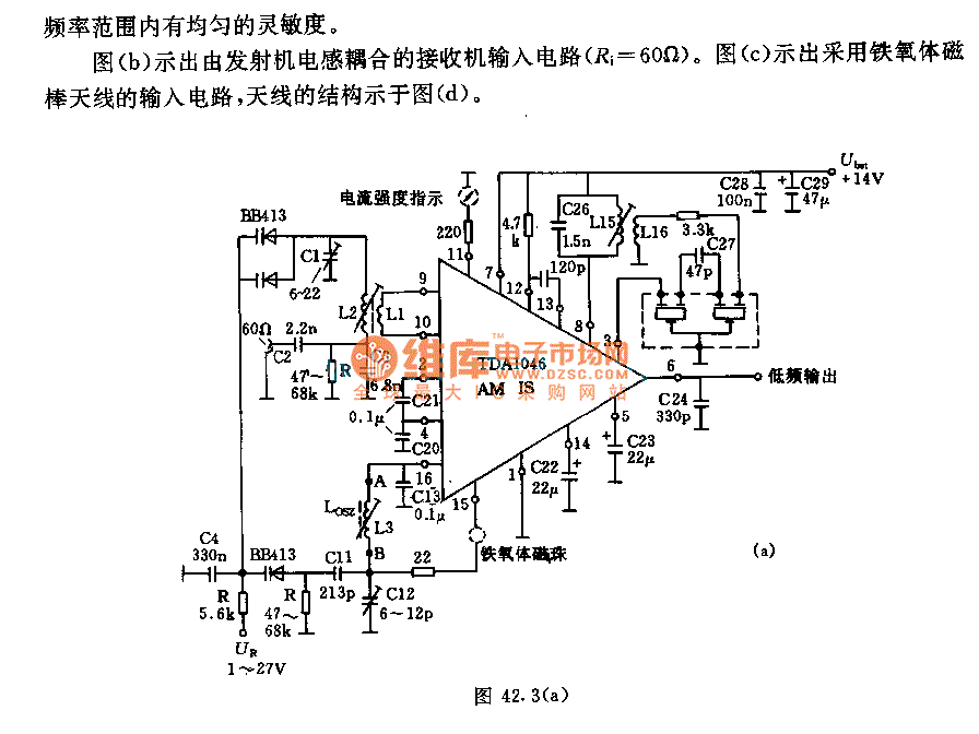
IC AM radio circuit
The receiver input circuit is powered by a 60Ω generator. A low-pass filter is employed to permit the entire frequency range while maintaining uniform sensitivity. The receiver input circuit is coupled with a transmitter inductive component (Ri = 60Ω). Additionally,...

tea5551t am radio receiver circuit design electronic project
The TEA5551T monolithic integrated radio circuit can be utilized to design an AM radio receiver, intended for use as a portable radio receiver with headphones. The TEA5551T radio receiver circuit encompasses all necessary components for a complete AM receiver, including...

Simple Am Radio
An AM radio can be constructed using a simple diode detector and an audio amplifier. A random length of wire typically serves as an antenna. LI is an adjustable ferrite loopstick similar to those used in transistor radios.
An AM radio...
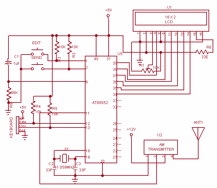
Wireless Data Communication system
This project is used to communicate or transmit a text message from one place to another place through wireless. The text message is encrypted by using the Microcontroller and the encrypted message was transmitted through wireless. At the receiver end...

UTC7642 1-Chip AM Radio Circuit
A low-cost vacuum cleaner system based on the P89LPC901 is introduced in this application note. The design hardware and software are thoroughly discussed. This system can also guide the design of other universal motor driving systems that require robust control...

AM Radio Receiver
The AM radio receiver circuit diagram is based on the single integrated circuit MK484. The components list includes: R9, R10 (6.8 ohms), R6 (100 ohms), R3 (1k ohms), R1 (4.7k ohms), R7 (5.6k ohms), R4 (10k ohms), R2 (100k ohms),...

Radio circuit
The circuit operates by utilizing a high-frequency section of the antenna to receive AM radio signals, amplifying radio-frequency signals at a selected vibration level of 465 kHz. The intermediate frequency (IF) signal is processed through an IF amplifier, followed by...

AM Radio
A MW AM radio like those you buy, or used to buy. Use just BC549 trannies, with the BC559 complement being allowed in the audio output stage. Buying RF antenna coils, oscillator coils and intermediate frequency transformers would be cheating...