


MICRO FM Bug
#FM
#bug
#electret microphone
#audio amplifier
#RF oscillator
#FET transistor
#wireless
#transmitter
#spy

Description: The circuit consists of three stages, an electret microphone, an audio amplifier and an RF oscillator. The electret microphone consists of only two parts - a FET transistor and a plastic diaphragm. There is nothing else inside the case. The 3-leaded FET has an input, output and earth lead. The mylar diaphragm has been permanently charged with a static charge and this is one of the secrets of the operation of the microphone. The FET transistor has a very high input impedance and because it is an active device, we call it a stage. The gain of this device is extremely high because it is able to amplify the charges from a charged surface to produce an output in the millivolt range.
The circuit described integrates three fundamental components to facilitate audio signal processing and transmission. The electret microphone serves as the initial stage, where sound waves are converted into electrical signals. This microphone employs a field-effect transistor (FET) that is crucial for its operation. The diaphragm, typically made of mylar, is pre-charged, allowing it to respond to acoustic pressure variations. When sound waves hit the diaphragm, it vibrates, causing variations in capacitance that the FET converts into an electrical signal. The FET, with its high input impedance, ensures minimal loading on the diaphragm, preserving the fidelity of the audio signal.
Following the microphone stage, the audio amplifier boosts the low-level signals produced by the FET. This amplifier stage typically consists of one or more transistor configurations that provide necessary gain while maintaining signal integrity. The design may include passive components like resistors and capacitors to filter noise and stabilize the gain.
The final stage of the circuit is the RF oscillator, which modulates the amplified audio signal onto a carrier frequency for transmission. This stage can utilize various oscillator designs, such as Colpitts or Hartley oscillators, depending on the desired frequency stability and output characteristics. The RF oscillator's output can be coupled to an antenna for wireless transmission of the audio signal, enabling applications in communication systems and audio broadcasting.
Overall, this circuit exemplifies the integration of audio sensing, amplification, and transmission, showcasing a fundamental approach to electronic audio systems.The circuit consists of three stages, an electret microphone, an audio amplifier and an RF oscillator. The electret microphone consists of only two parts - a FET transistor and a plastic diaphragm. There is nothing else inside the case. The 3-leaded FET has an input, output and earth lead. The mylar diaphragm has been permanently charged with a static charge and this is one of the secrets of the operation of the microphone.
The FET transistor has a very high input impedance and because it is an active device, we call it a stage. The gain of this device is extremely high because it is able to amplify the charges from a charged surface to produce an output in the millivolt ra
The circuit described integrates three fundamental components to facilitate audio signal processing and transmission. The electret microphone serves as the initial stage, where sound waves are converted into electrical signals. This microphone employs a field-effect transistor (FET) that is crucial for its operation. The diaphragm, typically made of mylar, is pre-charged, allowing it to respond to acoustic pressure variations. When sound waves hit the diaphragm, it vibrates, causing variations in capacitance that the FET converts into an electrical signal. The FET, with its high input impedance, ensures minimal loading on the diaphragm, preserving the fidelity of the audio signal.
Following the microphone stage, the audio amplifier boosts the low-level signals produced by the FET. This amplifier stage typically consists of one or more transistor configurations that provide necessary gain while maintaining signal integrity. The design may include passive components like resistors and capacitors to filter noise and stabilize the gain.
The final stage of the circuit is the RF oscillator, which modulates the amplified audio signal onto a carrier frequency for transmission. This stage can utilize various oscillator designs, such as Colpitts or Hartley oscillators, depending on the desired frequency stability and output characteristics. The RF oscillator's output can be coupled to an antenna for wireless transmission of the audio signal, enabling applications in communication systems and audio broadcasting.
Overall, this circuit exemplifies the integration of audio sensing, amplification, and transmission, showcasing a fundamental approach to electronic audio systems.The circuit consists of three stages, an electret microphone, an audio amplifier and an RF oscillator. The electret microphone consists of only two parts - a FET transistor and a plastic diaphragm. There is nothing else inside the case. The 3-leaded FET has an input, output and earth lead. The mylar diaphragm has been permanently charged with a static charge and this is one of the secrets of the operation of the microphone.
The FET transistor has a very high input impedance and because it is an active device, we call it a stage. The gain of this device is extremely high because it is able to amplify the charges from a charged surface to produce an output in the millivolt ra

200W Hybrid Audio Amplifier Circuit
Connecting two TDA2030 through inexpensive power transistors allows for the creation of an amplifier capable of delivering higher power. This can be achieved by utilizing the component values specified in the schematic.
To implement this circuit, two TDA2030 integrated circuits are...

Class B audio amplifier
The closer the two transistors are matched, the better the performance. It is advisable to use TIP41 and TIP42 transistors, which are closely matched NPN and PNP power transistors with a dissipation rating of 65 watts each. If a TIP41...

TA8136S Radio Control Transmitter Ic - Toshiba Semiconductor
TB6556FG is a 3-phase full-wave sine-wave PWM brushless motor controller. It features sine-wave PWM control and includes a built-in triangular-wave generator with a carrier cycle defined as fosc/252 (Hz). The device also offers a built-in lead angle control function that...
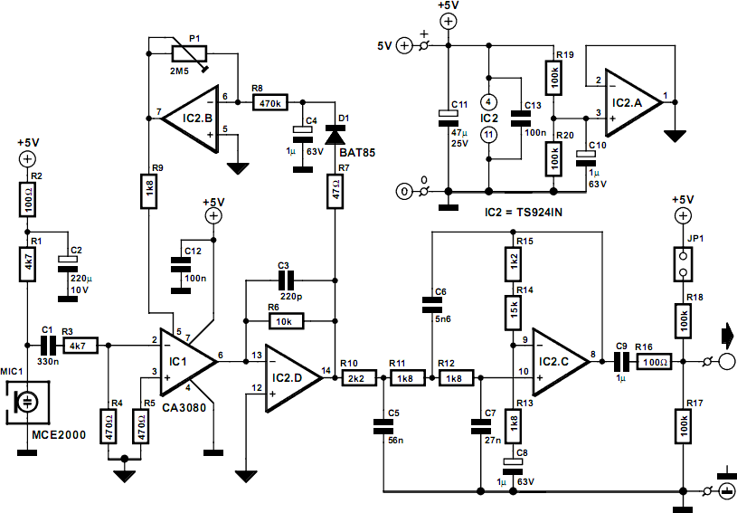
Compressor For Electret Microphone
The FM Remote Control Receiver, found in the Infra-red circuits section of this website, features a connector that provides an analogue output. To create a simple intercom or public address (P.A.) system, a microphone pre-amplifier is required to ensure the...

4x15Watt 12volt power audio amplifier
While I would have liked a 4 channel chip with about 20 Watt per channel, the local parts store didn't have any yet, so I opted for two TA8215AH stereo chips, selected by their low price in this particular store....

100 watt simple mosfet power amp
The schematic diagram of a 100-watt audio amplifier utilizing MOSFET technology. A comprehensive collection of electronic circuit diagrams is available, including a 100W RMS amplifier and a 0-30V stabilized variable power supply with current control.
The 100-watt audio amplifier schematic employs...

wireless telephone line spy circuit
This design outlines a phone bug circuit. The wireless telephone line spy circuit is capable of transmitting phone conversations to a nearby FM radio. The circuit must be connected to a standard phone line. In the circuit, the first transistor...

Audio Amplifier Diagram
The circuit is based on four integrated circuits: TL072, TL074, MN3101, and MN3004, which produce four output channels for surround audio, specifically targeting center, rear, front right, and front left audio. It is a compact amplifier capable of delivering 7W...

80 Watt stereo transmitter
This transmitter was designed from the ground up to provide very high sound quality, coupled with excellent frequency stability, reliability, etc. It can be used as a standalone transmitter to serve a medium-sized town, or as an exciter to drive...