


Misc RF Topics
#LO system
#diode ring
#VFO
#crystal oscillator
#band-pass filter
#amplifier
#SSB/CW
#transceiver
#mixing
#feedback

Description: The local oscillator (LO) system from the project titled "A Monoband SSB/CW Transceiver" in Chapter 6 of EMRFD. The low output (approximately -20 dBm) from a diode ring mixing a variable frequency oscillator (VFO) and crystal oscillator is triple-tuned band-pass filtered and then amplified to +8 dBm. The transmitter chain continues with additional mixing, band-pass filtering, and voltage amplification through a feedback amplifier chain, boosting the signal to around 300 mW. The circuits required to mix, filter, and amplify this RF chain present challenges for most amateur designers. In contrast, a typical initial transmitter constructed by a new builder often consists of a crystal oscillator, a keyed Class A buffer/amplifier, and possibly a Class C final amplifier, with no mixer required since a crystal is cut for the desired frequency. The focus was on power, achieving 0.25 to 1 watt into the antenna system. A notable example is the Tuna Tin 2 transmitter designed by the late Doug DeMaw, W1FB, which used only two stages. Although Doug's 1976 article aimed to assist Hams in building transmitters from readily available parts, kitted versions are still available today. Returning to transmit mixers, amateur designers typically start with a small portion of the transmit chain and gradually extend their experiments to the antenna port. In Fall 2010, an examination of basic transmit mixing was conducted to understand the involved complexities and expectations. Mixing signals is intricate, encompassing topics such as intercept point, conversion gain or loss, image noise suppression, noise figure, spurious/intermodulation products, and port isolation. For simplicity, only mixer port isolation and the reduction of spurious mixer products were investigated. A significant concern is that experimenters, as stewards of the airwaves, must construct exemplary transmitters with very low spurious outputs. Following the example of Wes, W7ZOI, and others, it is crucial that transmit chains maintain spurious frequencies at least 50-60 dB down from the carrier (dBc). As a web author and radio amateur, the goal is to avoid contributing to radio frequency interference (RFI) and to promote responsible practices in transmitter design.
The LO system described is a critical component of the transceiver's architecture, utilizing a diode ring mixer to combine signals from a VFO and a crystal oscillator. This configuration allows for flexibility in frequency selection while maintaining stability and precision. The initial output is subjected to a triple-tuned band-pass filter, which is essential for removing unwanted frequency components and ensuring that only the desired signal is amplified. The amplification stage raises the output to +8 dBm, which is a suitable level for further processing.
Following the initial amplification, the transmitter chain incorporates additional mixing stages, which are necessary for achieving the desired output frequency while maintaining signal integrity. The use of a feedback amplifier chain is a strategic choice, as it provides additional gain, boosting the signal to approximately 300 mW. This level of power is sufficient for effective transmission across various amateur radio bands.
The challenges associated with designing the RF chain, including mixing, filtering, and amplification, require a deep understanding of RF principles. The complexities of mixing signals involve considerations such as intercept points, which determine the linearity of the mixer, and conversion gain, which affects the overall efficiency of the system. Additionally, image noise suppression and noise figure are critical parameters that influence the quality of the transmitted signal.
Spurious and intermodulation products present significant challenges in transmitter design. The need to minimize these unwanted signals is paramount, as they can lead to interference with other communication systems. The focus on achieving at least 50-60 dB down from the carrier for spurious outputs aligns with best practices in amateur radio, ensuring that transmissions are clean and compliant with regulatory standards.
Overall, the described LO system and its associated circuitry represent a sophisticated approach to amateur radio transmission, emphasizing the importance of careful design and testing to achieve optimal performance while minimizing the risk of interference.The LO system from the project entitled A Monoband SSB/CW Transceiver in Chapter 6 of EMRFD. The mega low (about -20 dBm) output from a diode ring mixing a VFO and crystal oscillator is triple tuned band-pass filtered and then amplified to +8 dBm. Continuing on, the transmitter chain features more mixing, band-pass filtering and voltage amplification by a feedback
amplifier chain boosting the signal to around 300 mW. The circuits needed to mix, filter and amplify this RF chain would challenge most amateur designers ” me included. Contrast this with a typical first transmitter built by a new builder. Likely your first scratch homebrew transmitter consisted of a crystal oscillator, a keyed Class A buffer/amplifier and perhaps a Class C final amplifier.
No mixer was needed for we obtained a crystal cut on the frequency of choice. Our focus was power ” getting 0. 25 to 1 watt into our antenna system! A good example was the Tuna Tin 2 transmitter by the late Doug DeMaw, W1FB that only used 2 stages. Although Doug wrote his 1976 article for Hams to build a transmitter from parts found at home, kitted versions are sold today. Returning to transmit mixers ” as amateur designers, we likely need to start on a small portion of the transmit chain and then after developing some competency, slowly extend our experiments all the way to the antenna port.
In Fall 2010, I just examined some basic transmit mixing to get a feel for what`s involved and what to expect. Mixing signals is a complex affair encompassing topics such as intercept point, conversion gain or loss, image noise suppression, noise figure, spurious/intermodulation products and port isolation.
To keep things simple, only mixer port isolation and reducing spurious mixer products were examined. Before beginning, I express the following concern: We experimenters, as stewards of the airwaves, must build exemplary transmitters with very low spurious outputs. I follow the example of Wes, W7ZOI and others ” my transmit chains have spurious frequencies at least 50-60 dB down from the carrier (dBc).
As a web author and radio amateur, I never want to directly or indirectly contribute to RFI and hope you agree. If you plan to design a superheterodyne based transceiver, you`ll probably need to use a tran
The LO system described is a critical component of the transceiver's architecture, utilizing a diode ring mixer to combine signals from a VFO and a crystal oscillator. This configuration allows for flexibility in frequency selection while maintaining stability and precision. The initial output is subjected to a triple-tuned band-pass filter, which is essential for removing unwanted frequency components and ensuring that only the desired signal is amplified. The amplification stage raises the output to +8 dBm, which is a suitable level for further processing.
Following the initial amplification, the transmitter chain incorporates additional mixing stages, which are necessary for achieving the desired output frequency while maintaining signal integrity. The use of a feedback amplifier chain is a strategic choice, as it provides additional gain, boosting the signal to approximately 300 mW. This level of power is sufficient for effective transmission across various amateur radio bands.
The challenges associated with designing the RF chain, including mixing, filtering, and amplification, require a deep understanding of RF principles. The complexities of mixing signals involve considerations such as intercept points, which determine the linearity of the mixer, and conversion gain, which affects the overall efficiency of the system. Additionally, image noise suppression and noise figure are critical parameters that influence the quality of the transmitted signal.
Spurious and intermodulation products present significant challenges in transmitter design. The need to minimize these unwanted signals is paramount, as they can lead to interference with other communication systems. The focus on achieving at least 50-60 dB down from the carrier for spurious outputs aligns with best practices in amateur radio, ensuring that transmissions are clean and compliant with regulatory standards.
Overall, the described LO system and its associated circuitry represent a sophisticated approach to amateur radio transmission, emphasizing the importance of careful design and testing to achieve optimal performance while minimizing the risk of interference.The LO system from the project entitled A Monoband SSB/CW Transceiver in Chapter 6 of EMRFD. The mega low (about -20 dBm) output from a diode ring mixing a VFO and crystal oscillator is triple tuned band-pass filtered and then amplified to +8 dBm. Continuing on, the transmitter chain features more mixing, band-pass filtering and voltage amplification by a feedback
amplifier chain boosting the signal to around 300 mW. The circuits needed to mix, filter and amplify this RF chain would challenge most amateur designers ” me included. Contrast this with a typical first transmitter built by a new builder. Likely your first scratch homebrew transmitter consisted of a crystal oscillator, a keyed Class A buffer/amplifier and perhaps a Class C final amplifier.
No mixer was needed for we obtained a crystal cut on the frequency of choice. Our focus was power ” getting 0. 25 to 1 watt into our antenna system! A good example was the Tuna Tin 2 transmitter by the late Doug DeMaw, W1FB that only used 2 stages. Although Doug wrote his 1976 article for Hams to build a transmitter from parts found at home, kitted versions are sold today. Returning to transmit mixers ” as amateur designers, we likely need to start on a small portion of the transmit chain and then after developing some competency, slowly extend our experiments all the way to the antenna port.
In Fall 2010, I just examined some basic transmit mixing to get a feel for what`s involved and what to expect. Mixing signals is a complex affair encompassing topics such as intercept point, conversion gain or loss, image noise suppression, noise figure, spurious/intermodulation products and port isolation.
To keep things simple, only mixer port isolation and reducing spurious mixer products were examined. Before beginning, I express the following concern: We experimenters, as stewards of the airwaves, must build exemplary transmitters with very low spurious outputs. I follow the example of Wes, W7ZOI and others ” my transmit chains have spurious frequencies at least 50-60 dB down from the carrier (dBc).
As a web author and radio amateur, I never want to directly or indirectly contribute to RFI and hope you agree. If you plan to design a superheterodyne based transceiver, you`ll probably need to use a tran

1024kHz and 4kHz square-wave output circuit
The circuit SJT is a 1024 kHz warming crystal oscillator. The circuit is illustrated in the accompanying chart. Due to the low output signal level, a transistor (VT1) is employed as a buffer amplifier. The base bias resistor (R2) of...

marker generator
A resistor of 100K Ohm is connected between pin 10 and pin 11, while another resistor of 2K Ohm is present in the circuit. The fixed capacitor was determined through trial and error to achieve resonance with the crystal at...

Amp Gain Block
The feedback in this circuit is DC coupled, connecting directly from the plate of the second triode to the cathode of the first triode, as opposed to the earlier design which utilized AC coupled feedback. The previous version exhibited instability...

General-Purpose Output Amplifier Circuit
This general-purpose amplifier has a bandwidth of approximately 20 MHz and it uses an LM733/NE592 video amplifier integrated circuit. This circuit can be utilized as a line driver or as a LAN line driver.
The circuit employs the LM733/NE592 video amplifier...

HAM ATS3a digital
The stock ATS-3A transceiver has been modified to transmit BPSK31 signals, specifically "cq ok1iak." The firmware was altered to enable serial line control through the DASH paddle pin while in straight key mode, which disables the paddle in remote control...

How to connect a crystal oscillator to generate Square wave
To generate a 1 MHz square wave, it is advisable to use a higher frequency crystal and divide it down for two reasons: (1) 4 MHz crystals are generally more affordable and easier to procure than 1 MHz crystals; (2)...
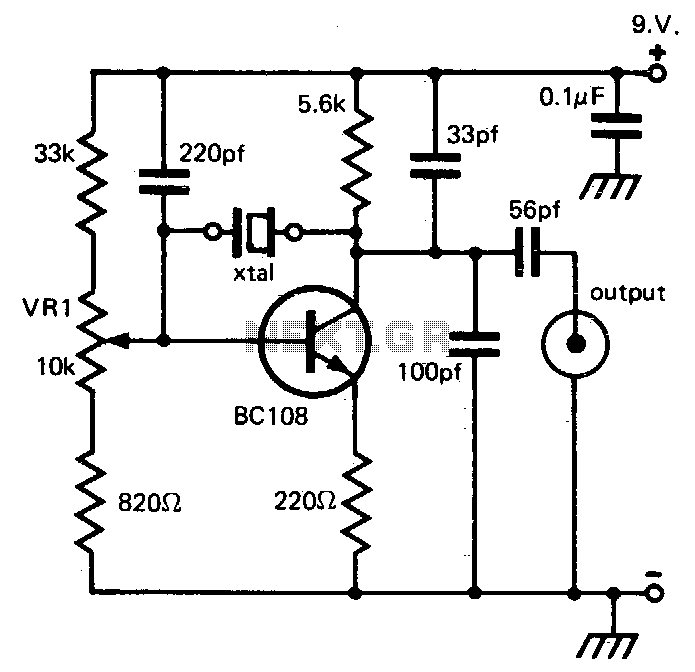
96Mhz crystal oscillator
This circuit provides reliable oscillation and an output close to one volt peak-to-peak. Power consumption is around 1 mA from a nine-volt supply.
The described circuit is likely a simple oscillator designed to generate a periodic waveform with a peak-to-peak voltage...

15-65MHz circuit diagram of the third harmonic
A circuit diagram illustrating the reliability of crystal startup, with power consumption significantly lower than the maximum allowed for the crystal. The transistor Q1 can be one of the following: 2N918, 2N3564, 2N5770, BF180, or BF200. The inductor L1 is...

QRP CW TRANSCEIVER
This is a 3-W, single-circuit board, VFO-controlled CW transceiver for 40 or 30 meters, featuring a direct-conversion receiver with audio filtering, Receiver Incremental Tuning (RIT), and speaker level audio volume. The transmit frequency is generated by Q1 and its associated...