


Modern FM Converter

Description: Here is my design for a modern receiving converter for pre-war FM sets. Accordingly, this article presents a design for listening to present day FM stations on a prewar FM set based on a MOSFET transistor and a TTL (transistor-transistor logic) packaged oscillator. Someone else might have done it with vacuum tubes, but this design suits me fine. It is all a matter of taste. More: My FM radio station of choice is at 101.1 MHz. I specialize in FM only radios, so listening to this station is no problem on most of my sets. But prior to WWII, the FM radio band covered 42 to 50 MHz. These prewar FM radios are nearly useless. Turn one on.
The proposed design features a modern receiving converter tailored for pre-war FM radio sets, which traditionally operate within the 42 to 50 MHz frequency range. The converter utilizes a MOSFET transistor for its amplification and a TTL packaged oscillator for frequency generation, allowing compatibility with contemporary FM stations, such as the chosen frequency of 101.1 MHz.
The circuit begins with the input stage, where the audio signal from the antenna is fed into a bandpass filter, designed to isolate the desired frequency range while attenuating unwanted signals. The filtered signal is then amplified by the MOSFET transistor, which provides the necessary gain to drive the subsequent stages of the circuit.
Following the amplification, the TTL oscillator generates a local oscillator signal at a frequency that, when mixed with the incoming FM signal, produces an intermediate frequency (IF) suitable for further processing. The mixing process can be achieved using a diode mixer or an active mixer configuration, which combines the amplified RF signal with the local oscillator signal to create the IF output.
The IF signal is then passed through another bandpass filter to remove any unwanted harmonics or spurious signals generated during the mixing process. This filtered IF signal is subsequently demodulated to recover the original audio signal. Demodulation can be accomplished using various techniques, such as a phase-locked loop (PLL) or a simple envelope detector, depending on the desired fidelity and complexity of the design.
Finally, the demodulated audio signal is amplified again, if necessary, to drive the audio output stage, which can be connected to the pre-war FM radio's audio input. This entire system allows users to enjoy modern FM broadcasting while utilizing their vintage radio equipment, effectively bridging the gap between historical technology and contemporary audio enjoyment.Here is my design for a modern receiving converter for pre-war FM sets. Accordingly, this article presents a design for listening to present day FM stations on a prewar FM set based on a MOSFET transistor and a TTL (transistor-transistor logic) packaged oscillator. Someone else might have done it with vacuum tubes, but this design suits me fine. It is all a matter of taste. My FM radio station of choice is at 101.1 MHz. I specialize in FM only radios, so listening to this station is no problem on most of my sets. But prior to WWII, the FM radio band covered 42 to 50 MHz. These prewar FM radios are nearly useless. Turn one on
The proposed design features a modern receiving converter tailored for pre-war FM radio sets, which traditionally operate within the 42 to 50 MHz frequency range. The converter utilizes a MOSFET transistor for its amplification and a TTL packaged oscillator for frequency generation, allowing compatibility with contemporary FM stations, such as the chosen frequency of 101.1 MHz.
The circuit begins with the input stage, where the audio signal from the antenna is fed into a bandpass filter, designed to isolate the desired frequency range while attenuating unwanted signals. The filtered signal is then amplified by the MOSFET transistor, which provides the necessary gain to drive the subsequent stages of the circuit.
Following the amplification, the TTL oscillator generates a local oscillator signal at a frequency that, when mixed with the incoming FM signal, produces an intermediate frequency (IF) suitable for further processing. The mixing process can be achieved using a diode mixer or an active mixer configuration, which combines the amplified RF signal with the local oscillator signal to create the IF output.
The IF signal is then passed through another bandpass filter to remove any unwanted harmonics or spurious signals generated during the mixing process. This filtered IF signal is subsequently demodulated to recover the original audio signal. Demodulation can be accomplished using various techniques, such as a phase-locked loop (PLL) or a simple envelope detector, depending on the desired fidelity and complexity of the design.
Finally, the demodulated audio signal is amplified again, if necessary, to drive the audio output stage, which can be connected to the pre-war FM radio's audio input. This entire system allows users to enjoy modern FM broadcasting while utilizing their vintage radio equipment, effectively bridging the gap between historical technology and contemporary audio enjoyment.Here is my design for a modern receiving converter for pre-war FM sets. Accordingly, this article presents a design for listening to present day FM stations on a prewar FM set based on a MOSFET transistor and a TTL (transistor-transistor logic) packaged oscillator. Someone else might have done it with vacuum tubes, but this design suits me fine. It is all a matter of taste. My FM radio station of choice is at 101.1 MHz. I specialize in FM only radios, so listening to this station is no problem on most of my sets. But prior to WWII, the FM radio band covered 42 to 50 MHz. These prewar FM radios are nearly useless. Turn one on

280 Watt MOSFET Power Amplifier
This amplifier is designed to be as flexible as possible, with no bad habits. Indeed, it will operate stably with supply voltages as low as +/-5V (completely pointless, but interesting), all the way to the maximum supply voltage of +/-70V....

Transistorized Auditory Gimmick
This circuit first appeared in "The Braille Technical Press," edited by Robert W. Gunderson, in 1955. Gunderson, W2JIO, designed this "gimmick" to read transmitter meters. It has appeared many times over a 20-year period, including in commercial aids and appliances...

High power mosfet amplifier circuit ideas
The power amplifier circuit utilizing MOSFET technology has gained significant popularity due to its aggressive sound characteristics when compared to traditional transistors and integrated circuits. It offers both low-frequency and high-frequency responses and is known for its durability. Generally, when...
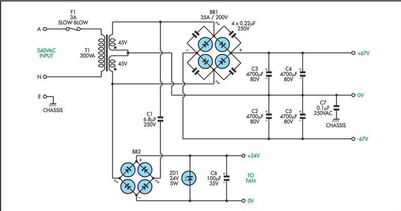
200W MOSFET Power Amplifier Schematic Diagram
This circuit utilizes a MOSFET amplifier as the primary component for boosting audio signals. It is designed to drive a speaker with an impedance of 8 Ohms and a power output exceeding 200W. Additionally, a suitable power supply circuit is...

transistors How does this circuit diagram work
R2 controls the charging speed of capacitor C1. At a specific charge level, C1 triggers transistors Q1 and Q2, which release a 9-volt pulse. This pulse generates a clicking sound. The discharge process of the capacitor involves it charging gradually...

50 watt power MOSFET amplifier circuit diagram
This is a MOSFET transistor-based power amplifier circuit that operates within a voltage range of +35V to -35V. The input voltage is pre-filtered and pre-amplified before being applied to the MOSFET switch. The pre-audio amplifier consists of a differential amplifier...

easy build motocycle alarm
The circuit requires two transistors to drive a relay, which acts as a switch to activate a buzzer. Any number of normally-open switches may be applied. Mercury switches should be installed to ensure they close when the steering is engaged....

mosfet Reverse polarity protection
When a reverse voltage of 10V is applied to the source while the drain is grounded, the gate-source voltage (Vgs) becomes -10V. This voltage is significantly above the threshold, which allows the MOSFET to remain in the saturation region, enabling...

Mosfet Mixer-Oscillator Circuit For Am Receivers Circuit
This circuit is an enhanced front end for upgrading a transistor AM receiver. This front end is beneficial when the radio is intended to function as a tunable IF amplifier with shortwave converters.
The circuit described serves as a sophisticated enhancement...