


PreamplifierCircuit DCF77
#DCF77
#preamplifier
#microcontroller
#ferrite antenna
#time signal
#radio-controlled clock
#demodulation
#Germany
#long-range
#RF reception
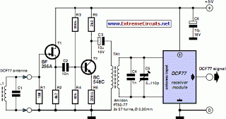
Description: DCF77 Preamplifier Circuit Diagram A popular project among microcontroller enthusiasts is to build a radio-controlled clock. Small receiver boards are available, equipped with a pre-adjusted ferrite antenna, that receive and demodulate the DCF77 time signal broadcast from Mainflingen in Germany. DCF77 has a range of approximately 1,000 miles. All that is required from the microcontroller is to decode the signal and display the results. The quality of reception achieved by these pre-manufactured boards generally correlates with their price. In areas with marginal reception, a higher quality receiver is necessary, and a small selective preamplifier stage typically enhances performance. The original ferrite antenna is desoldered from the receiver module and connected to the preamplifier's input. This input features a source follower (T1) that has minimal damping effect on the resonant circuit. A bipolar transistor (T2) provides approximately 5 dB of gain. The output signal is coupled to the antenna input of the DCF77 module via a transformer. The secondary of the transformer, along with capacitors C4 and C5, forms a resonant circuit that must be tuned to center on the carrier frequency. An oscilloscope is required for this adjustment, and a signal generator set to produce a 77.5 kHz sine wave is also beneficial. This signal is introduced, at an amplitude of a few millivolts, into the antenna input. With the oscilloscope connected across C4 and C5 to monitor the output resonant circuit signal, trimmer capacitor C5 is adjusted until maximum amplitude is observed. It is crucial that the transformer used is suitable for constructing a resonant circuit at the carrier frequency. The prototype utilized an FT50-77 core from Amidon, on which two 57-turn windings were made. It is also possible to adjust the resonant frequency of the circuit using a transformer with an adjustable core. In this scenario, the trimmer capacitor may be omitted.
The DCF77 preamplifier circuit is designed to enhance the reception of the DCF77 time signal, which is crucial for applications such as radio-controlled clocks. The circuit utilizes a combination of a source follower and a bipolar transistor to amplify the weak signals received by the ferrite antenna.
The source follower (T1), which is the first stage of the preamplifier, serves to buffer the input signal while presenting a high input impedance and low output impedance. This configuration allows for minimal signal loss and ensures that the resonant characteristics of the antenna are preserved. The bipolar transistor (T2) provides additional gain to the signal, amplifying it by approximately 5 dB. This gain is significant for improving the signal-to-noise ratio, especially in areas where the DCF77 signal may be weak or distorted.
The transformer used in the circuit is a critical component, as it couples the amplified signal to the DCF77 module while also forming part of the resonant circuit with capacitors C4 and C5. This resonant circuit must be precisely tuned to the carrier frequency of 77.5 kHz to ensure optimal performance. The tuning process involves using an oscilloscope to monitor the output signal across the capacitors while adjusting the trimmer capacitor (C5) for maximum amplitude.
The choice of transformer is also important; it must be capable of resonating at the desired frequency without introducing significant losses. The FT50-77 core from Amidon, used in the prototype, is a suitable choice due to its characteristics, which allow for effective winding configurations. The circuit can also accommodate transformers with adjustable cores, providing flexibility in tuning without the need for a trimmer capacitor.
Overall, the DCF77 preamplifier circuit is a well-engineered solution for enhancing the reception of time signals, making it an essential component for reliable operation of radio-controlled clocks. Proper assembly and tuning of the circuit will yield improved performance and accuracy in timekeeping applications.DCF77 Preamplifier Circuit DiagramA popular project among microcontroller aficionados is to build a radio-controlled clock. Tiny receiver boards are available, with a pre-adjusted ferrite antenna, that receive and demodulate the DCF77 time signal broadcast from Mainf lingen in Germany.
DCF77 has a range of about 1, 000 miles. All the microcontrolle r need do is decode the signal and output the results on a display. The reception quality achieved by these ready-made boards tends to be proportional to their price. In areas of marginal reception a higher quality receiver is needed, and a small selective preamplifier stage will usually improve the situation further. The original ferrite antenna is desoldered from the receiver module and connected to the input of the preamplifier.
This input consists of a source follower (T1) which has very little damping effect on the resonant circuit. A bipolar transistor (T2) provides a gain of around 5 dB. The output signal is coupled to the antenna input of the DCF77 module via a transformer. DCF77 Preamplifier Circuit Diagram The secondary of the transformer, in conjunction with capacitors C4 and C5, forms a resonant circuit which must be adjusted so that it is centered on the carrier frequency.
An oscilloscope is needed for this adjustment, and a signal generator, set to generate a 77. 5 kHz sine wave, is also very useful. This signal is fed, at an amplitude of a few milli-volts, into the antenna input. With the oscilloscope connected across C4 and C5 to monitor the signal on the output resonant circuit, trimmer C5 is adjusted until maximum amplitude is observed. It is essential that the transformer used is suitable for constructing a resonant circuit at the carrier frequency.
Our proto-type used a FT50-77 core from Amidon on which we made two 57-turn windings. It is also possible to trim the resonant frequency of the circuit by using a transformer whose core can be adjusted in and out. In this case, of course, the trimmer capacitor can be dispensed with. Rainer Reusch Elektor Electronics 2008
The DCF77 preamplifier circuit is designed to enhance the reception of the DCF77 time signal, which is crucial for applications such as radio-controlled clocks. The circuit utilizes a combination of a source follower and a bipolar transistor to amplify the weak signals received by the ferrite antenna.
The source follower (T1), which is the first stage of the preamplifier, serves to buffer the input signal while presenting a high input impedance and low output impedance. This configuration allows for minimal signal loss and ensures that the resonant characteristics of the antenna are preserved. The bipolar transistor (T2) provides additional gain to the signal, amplifying it by approximately 5 dB. This gain is significant for improving the signal-to-noise ratio, especially in areas where the DCF77 signal may be weak or distorted.
The transformer used in the circuit is a critical component, as it couples the amplified signal to the DCF77 module while also forming part of the resonant circuit with capacitors C4 and C5. This resonant circuit must be precisely tuned to the carrier frequency of 77.5 kHz to ensure optimal performance. The tuning process involves using an oscilloscope to monitor the output signal across the capacitors while adjusting the trimmer capacitor (C5) for maximum amplitude.
The choice of transformer is also important; it must be capable of resonating at the desired frequency without introducing significant losses. The FT50-77 core from Amidon, used in the prototype, is a suitable choice due to its characteristics, which allow for effective winding configurations. The circuit can also accommodate transformers with adjustable cores, providing flexibility in tuning without the need for a trimmer capacitor.
Overall, the DCF77 preamplifier circuit is a well-engineered solution for enhancing the reception of time signals, making it an essential component for reliable operation of radio-controlled clocks. Proper assembly and tuning of the circuit will yield improved performance and accuracy in timekeeping applications.DCF77 Preamplifier Circuit DiagramA popular project among microcontroller aficionados is to build a radio-controlled clock. Tiny receiver boards are available, with a pre-adjusted ferrite antenna, that receive and demodulate the DCF77 time signal broadcast from Mainf lingen in Germany.
DCF77 has a range of about 1, 000 miles. All the microcontrolle r need do is decode the signal and output the results on a display. The reception quality achieved by these ready-made boards tends to be proportional to their price. In areas of marginal reception a higher quality receiver is needed, and a small selective preamplifier stage will usually improve the situation further. The original ferrite antenna is desoldered from the receiver module and connected to the input of the preamplifier.
This input consists of a source follower (T1) which has very little damping effect on the resonant circuit. A bipolar transistor (T2) provides a gain of around 5 dB. The output signal is coupled to the antenna input of the DCF77 module via a transformer. DCF77 Preamplifier Circuit Diagram The secondary of the transformer, in conjunction with capacitors C4 and C5, forms a resonant circuit which must be adjusted so that it is centered on the carrier frequency.
An oscilloscope is needed for this adjustment, and a signal generator, set to generate a 77. 5 kHz sine wave, is also very useful. This signal is fed, at an amplitude of a few milli-volts, into the antenna input. With the oscilloscope connected across C4 and C5 to monitor the signal on the output resonant circuit, trimmer C5 is adjusted until maximum amplitude is observed. It is essential that the transformer used is suitable for constructing a resonant circuit at the carrier frequency.
Our proto-type used a FT50-77 core from Amidon on which we made two 57-turn windings. It is also possible to trim the resonant frequency of the circuit by using a transformer whose core can be adjusted in and out. In this case, of course, the trimmer capacitor can be dispensed with. Rainer Reusch Elektor Electronics 2008

home security system
The fundamental design of this project employs an Atmel AT89S8252-24PC Microcontroller, which features 2KB of EEPROM for runtime data storage. An ADC0838CCN analog-to-digital converter will be utilized to process up to eight inputs from sensor devices, including passive infrared sensors...

preamp circuit 3
During a Digital Projects Lab, the professor suggested incorporating more circuit-level work into a project. To achieve this, a preamplifier was designed, which included an infrared (IR) remote control to replace a previously built version. The earlier preamplifier functioned well...

Augmenting a Microcontroller
Microcontrollers (MCUs) are versatile integrated circuits that enhance the functionality of electronics, robotics, and other projects. However, they...
Microcontrollers (MCUs) serve as the central processing unit in a variety of electronic applications, offering programmable control that allows for complex functionalities in...
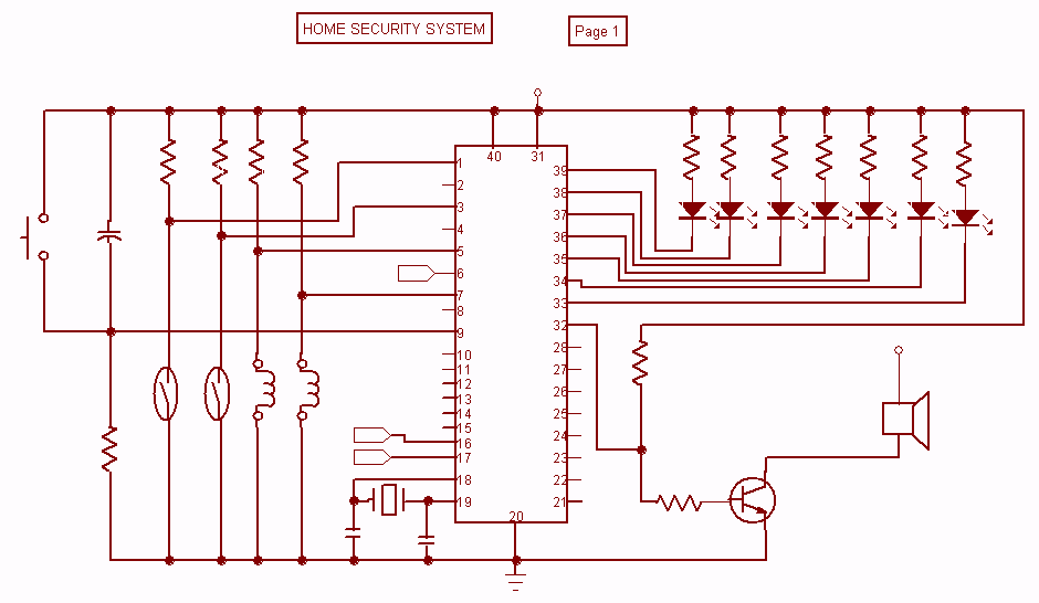
Home Security System with microcontroller
Security is a prime concern in our day-to-day life. Everyone wants to be as much secure as possible. An access control for doors forms a vital link in a security chain. The Microcontroller based Home Security System can be adopted...

repair microcontroller circuit
The difference between these two ICs. A microcontroller is a specialized type of microprocessor designed to be self-sufficient and cost-effective, while a microprocessor is typically intended for general-purpose use, such as in personal computers (PCs). The microcontroller integrates several useful...

Preamplifier with LA3161
Preamplifier with LA3161. Preamplifiers are utilized to amplify low-level signals, such as those from microphones and tape heads, before they are sent to power amplifiers.
The LA3161 is a versatile integrated circuit designed for use in audio preamplification applications. It is...

Microcontroller Based Telephone Remote Control Circuit
This device enables remote control of various appliances (up to eight with suitable add-on expansion boards) such as lights, water heaters, air conditioning, plant watering systems, alarms, etc., via a relay. It allows users to perform actions such as watering...
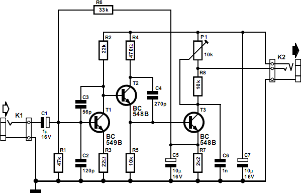
HiFi preamplifier for computer soundcard circuit
This circuit is designed for use with inductive pick-up elements and dynamic microphones. Most soundcards feature a line input and a separate input for electret (condenser) microphones. To connect an inductive tape recorder head or a dynamic microphone, an additional...

Microcontroller-based automatic night light circuit
While discussing an all-linear automatic night light circuit, it was mentioned that an MCU-based Automatic Night Light Controller (ANLC) was being tested. The firmware has been tweaked since then. Recently, the sensor was installed outdoors and connected to control 220VAC...