


QuickChip Design Example 2Low Power Silicon BJT LNA for 1.9GHz
#LNA
#low power
#1.9GHz
#silicon BJT
#monolithic
#bias circuit
#RF amplifier
#wireless communication
#microwave
#signal amplification
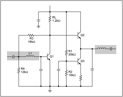
Description: This document presents a very low-power monolithic 1.9GHz silicon Low Noise Amplifier (LNA) that operates with a total current consumption of 1.75mA, which includes the bias circuit.
The described Low Noise Amplifier (LNA) operates at a frequency of 1.9GHz, making it suitable for various wireless communication applications, such as mobile phones and satellite communications. The monolithic design indicates that the entire circuit is integrated onto a single silicon chip, which enhances performance by reducing parasitic capacitance and inductance associated with discrete components.
The total current draw of 1.75mA is particularly noteworthy as it signifies a low-power operation, which is essential for battery-powered devices. The inclusion of the bias circuit within this current specification ensures that the LNA maintains optimal performance across varying temperature and voltage conditions, thereby providing consistent gain and noise figure.
In terms of performance metrics, the LNA is expected to exhibit a low noise figure, which is crucial for amplifying weak signals without introducing significant additional noise. The device's gain, input and output impedance, and linearity should be characterized to ensure compatibility with subsequent stages in a receiver chain.
The circuit design may employ various techniques to achieve low power consumption while maintaining high performance, such as using cascode configurations, current steering, and optimized transistor sizing. Additionally, the integration of on-chip passive components can further minimize the overall footprint of the device, making it ideal for compact designs.
Overall, the 1.9GHz silicon LNA represents a significant advancement in low-power RF amplification technology, suitable for modern communication systems that demand both efficiency and high performance.Presented in this letter is a very low-power monolithic 1.9GHz silicon LNA which draws a total current of 1.75mA including bias circuit..
The described Low Noise Amplifier (LNA) operates at a frequency of 1.9GHz, making it suitable for various wireless communication applications, such as mobile phones and satellite communications. The monolithic design indicates that the entire circuit is integrated onto a single silicon chip, which enhances performance by reducing parasitic capacitance and inductance associated with discrete components.
The total current draw of 1.75mA is particularly noteworthy as it signifies a low-power operation, which is essential for battery-powered devices. The inclusion of the bias circuit within this current specification ensures that the LNA maintains optimal performance across varying temperature and voltage conditions, thereby providing consistent gain and noise figure.
In terms of performance metrics, the LNA is expected to exhibit a low noise figure, which is crucial for amplifying weak signals without introducing significant additional noise. The device's gain, input and output impedance, and linearity should be characterized to ensure compatibility with subsequent stages in a receiver chain.
The circuit design may employ various techniques to achieve low power consumption while maintaining high performance, such as using cascode configurations, current steering, and optimized transistor sizing. Additionally, the integration of on-chip passive components can further minimize the overall footprint of the device, making it ideal for compact designs.
Overall, the 1.9GHz silicon LNA represents a significant advancement in low-power RF amplification technology, suitable for modern communication systems that demand both efficiency and high performance.Presented in this letter is a very low-power monolithic 1.9GHz silicon LNA which draws a total current of 1.75mA including bias circuit..

S1L9251X Cd-rom 48x Rf Amp Semiconductor
The SA1021 integrated radio receiver circuit is designed for portable radios, supporting both stereo and mono output while emphasizing minimal peripheral components for compact size and low cost. It is fully compatible with applications utilizing the low-voltage micro tuning system...

RF Amplifier For FM 88-108 MHzCircuit With Double Transistor
The following circuit illustrates an RF amplifier designed for FM frequencies ranging from 88 to 108 MHz with a broadband configuration. This circuit utilizes the BLV10 transistor.
The RF amplifier circuit operates within the FM broadcast band, which is crucial for...

TMB-1 Tri-Mode Buffer Amplifier Box
The TMB-1 is an RF amplifier unit and receiving accessory compatible with low-impedance broadband loops, high-impedance terminated loops (such as Pennant, Flag, or Kaz Delta), and whip (telescoping rod) antennas. This design is optimized for operation within the frequency range...
QSK 2KW
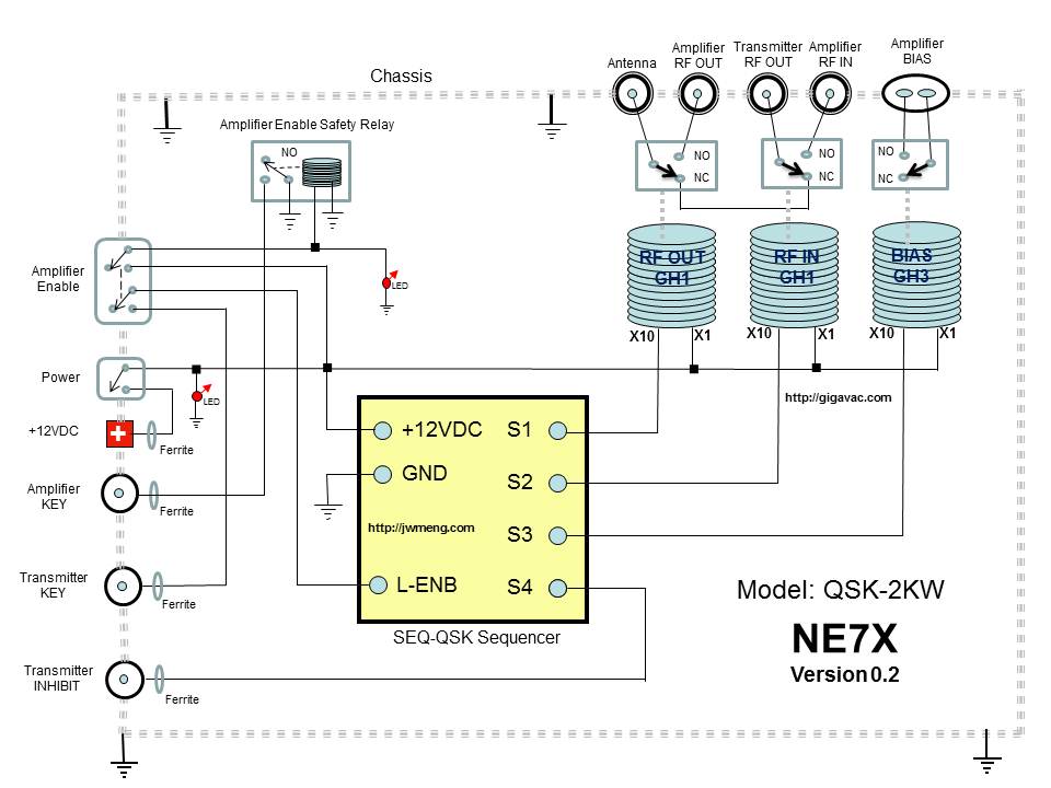
The QSK-2KW is an external RF T/R interface device that connects to any RF vacuum tube amplifier. It provides full high-speed RF amplifier T/R switching for CW or digital break-in operation. The QSK-2KW requires a low current keying input, allowing...

Simple Cable TV Amplifier Circuit
This cable TV amplifier circuit is an RF amplifier designed for quick installation between two coaxial cables. Both the input and output impedances are compatible with 75-ohm cables. The main amplifier is the T1 transistor, while T2 functions as an...

4 watt 900mhz rf amplifier
This RF amplifier circuit delivers a power output of 4 Watts at a frequency of 900 MHz. It utilizes Wilkinson power dividers in the base and collector circuits of transistors Q2 and Q3. Two SD1853 driver application transistors are paralleled...

RF isolation amplifier
This wideband RF isolation amplifier has a frequency response of 0.5 to 400 MHz ± 0.5 dB. This two-stage amplifier can be utilized in applications that require high reverse isolation, such as receiver intermediate-frequency (IF) strips and frequency distribution systems....

Wideband RF Amplifier
This circuit consists of wideband RF amplifiers that utilize current-feedback components such as the THS3202. The THS3202 was selected for its fast slew rate and wide bandwidth. The amplifier voltage gain of this circuit is 20, while the stage voltage...

20w rf fm amplifier circuit
This FM RF amplifier utilizes two transistors from Philips: the BLV 10 and the BLW 87. The two RF transistors are configured in a chic C arrangement, providing an overall gain of 21 dB (100 times) with an efficiency of...