


RF Isolator
#RF isolator
#one-way signal
#ferrite
#magnet
#high frequency
#non-linear
#signal isolation
#test port
#input/output

Description: An RF isolator is a seemingly magic device that allows signals to pass in only one direction. Signals applied to the input port are sent to the test port and signals coming into the test port can only go to the output port. This one-way property is usually accomplished with special non-linear ferrite/magnet structures operating at very high frequencies. More: For a typical setup the test generator is connected to the input port, the antenna or device to be tested is connected to the test port, and a signal level monitor is connected to the output port. When the test port is terminated with 50 ohms, no energy
An RF isolator, also known as a directional coupler, is a critical component in radio frequency applications, particularly in testing and measurement setups. The primary function of an RF isolator is to ensure that signals can only flow in one direction, effectively preventing reflections and potential damage to sensitive equipment. This is achieved through the use of non-linear ferrite materials that exhibit unique magnetic properties when exposed to high-frequency signals.
In a typical RF isolator circuit, there are three main ports: the input port, the test port, and the output port. The input port is where the RF signal is introduced, typically from a test generator. The test port is connected to the device under test (DUT) or an antenna, while the output port is linked to a signal level monitor or any other measurement device. The isolator's design ensures that signals traveling from the input to the test port are transmitted effectively, while any signals attempting to travel in the reverse direction from the test port to the input port are attenuated.
The operational principle of the RF isolator relies on the interaction of the RF signal with the ferrite material, which is often placed within a magnetic field. When a signal enters the isolator, the ferrite material's non-linear characteristics allow it to pass through in the intended direction. However, if a signal attempts to return from the test port to the input port, the ferrite's properties cause it to be absorbed or reflected, thus protecting the input circuitry.
For optimal performance, the test port is typically terminated with a 50-ohm load, which is a standard impedance in RF applications. This termination allows for maximum power transfer and minimizes reflections, ensuring that the isolator operates effectively without introducing additional losses. The design of RF isolators can vary, but they are often housed in compact enclosures to facilitate integration into larger systems.
Overall, the RF isolator is an essential component for ensuring signal integrity in high-frequency applications, making it invaluable in laboratory settings, telecommunications, and various RF engineering tasks.An RF isolator is a seemingly magic device that allows signals to pass in only one direction. Signals applied to the input port are sent to the test port and signals coming into the test port can only go to the output port. This one-way property is usually accomplished with special non-linear ferrite/magnet structures operating at very high frequencies.
For a typical setup the test generator is connected to the input port, the antenna or device to be tested is connected to the test port, and a signal level monitor is connected to the output port. When the test port is terminated with 50 ohms, no energy
An RF isolator, also known as a directional coupler, is a critical component in radio frequency applications, particularly in testing and measurement setups. The primary function of an RF isolator is to ensure that signals can only flow in one direction, effectively preventing reflections and potential damage to sensitive equipment. This is achieved through the use of non-linear ferrite materials that exhibit unique magnetic properties when exposed to high-frequency signals.
In a typical RF isolator circuit, there are three main ports: the input port, the test port, and the output port. The input port is where the RF signal is introduced, typically from a test generator. The test port is connected to the device under test (DUT) or an antenna, while the output port is linked to a signal level monitor or any other measurement device. The isolator's design ensures that signals traveling from the input to the test port are transmitted effectively, while any signals attempting to travel in the reverse direction from the test port to the input port are attenuated.
The operational principle of the RF isolator relies on the interaction of the RF signal with the ferrite material, which is often placed within a magnetic field. When a signal enters the isolator, the ferrite material's non-linear characteristics allow it to pass through in the intended direction. However, if a signal attempts to return from the test port to the input port, the ferrite's properties cause it to be absorbed or reflected, thus protecting the input circuitry.
For optimal performance, the test port is typically terminated with a 50-ohm load, which is a standard impedance in RF applications. This termination allows for maximum power transfer and minimizes reflections, ensuring that the isolator operates effectively without introducing additional losses. The design of RF isolators can vary, but they are often housed in compact enclosures to facilitate integration into larger systems.
Overall, the RF isolator is an essential component for ensuring signal integrity in high-frequency applications, making it invaluable in laboratory settings, telecommunications, and various RF engineering tasks.An RF isolator is a seemingly magic device that allows signals to pass in only one direction. Signals applied to the input port are sent to the test port and signals coming into the test port can only go to the output port. This one-way property is usually accomplished with special non-linear ferrite/magnet structures operating at very high frequencies.
For a typical setup the test generator is connected to the input port, the antenna or device to be tested is connected to the test port, and a signal level monitor is connected to the output port. When the test port is terminated with 50 ohms, no energy

10Mhz coaxial line driver
The circuit is ideal for high-frequency line driving systems that necessitate a wide power bandwidth at elevated output current levels. The integrated circuit used is HA2530. The bandwidth of the circuit is constrained solely by the single pole response of...

7MHz high frequency carrier oscillator
The 2SA130 transistor is used in an oscillator circuit with an oscillation frequency of 7 MHz. The power supply voltage is 6V, and the load is a frequency-selective resonant circuit with a quality factor of 600.
The circuit utilizes the 2SA130...

egan fet silicon power shoot out volume 10 high frequency resonant converters
Distributed power systems are commonly used in telecommunications, networking, and high-end server applications, utilizing a 48 V bus voltage derived from the telecom industry. This 48 V bus supplies several isolated point-of-load (POL) converters that power the end loads, with...

High frequency signal generator
A tapped-coil Colpitts oscillator is utilized at Q1 to deliver four tuning ranges: 1.7 to 3.131 MHz, 3.0 to 5.6 MHz, 5.0 to 12 MHz, and 11.5 to 31 MHz. A Zener diode (D2) is incorporated at Q1 to reduce...
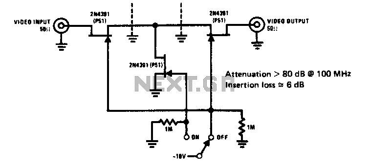
High frequency switch
The 2N4391 features a low ON resistance of 30 ohms and a high OFF impedance of less than 0 pF when in the off state. With appropriate layout and an optimal switch configuration, the stated performance can be easily attained.
The...

ISO100 sensing signal isolation amplifier
A bridge sensor output signal precision differential instrumentation amplifier with adjustable gain IC1 amplified signal IS0100. The gain of IC1 is determined by the external resistor Rc. The IC2 current source output is sent to drive the bridge sensor, while...

High Frequency Colpitts Crystal Oscillator
Op-amps have been widely used in low-frequency oscillators.
Op-amps, or operational amplifiers, are versatile components frequently utilized in the design of low-frequency oscillators. These devices are capable of generating periodic waveforms, such as sine, square, or triangular waves, which are essential...

High Frequency Waveform GeneratorCircuit
A high-frequency waveform generator is highly beneficial for electronic experimentation and design. This circuit generates sine wave oscillations; however, it can be modified to produce triangle or square wave functions. The frequency can be controlled using current. By disconnecting the...

High Frequency Switch
This is a high-frequency switch circuit. This circuit utilizes the 2N4391 transistor. When in the off state, it provides a high off-impedance of less than 0.2 pF and exhibits a low on-resistance.
The high-frequency switch circuit designed with the 2N4391 transistor...