


RF meter probe
#RF meter
#probe
#multimeter
#rectifier
#germanium diode
#high speed diode
#measurement
#low level RF
#electronics testing

Description: This probe is useful for any low level RF work, and simply connects to your multimeter. The voltage shown will not be accurate, since this is a rectifier probe, but the measurements are good enough for you to be able to determine where the RF stops, or if a stage is not giving the gain you think it should. The circuit could hardly be simpler. The diode must be a high speed type, and germanium is ideal and cheap. Do not use an ordinary silicon diode - it won't work! House the probe itself in some plastic tubing (an old pen barrel would work well), and use a sharpened nail for the probe, and an alligator clip on the ground lead. Keep the ground lead reasonably short for best performance. The coax can be anything that you have to hand. In fact, high capacitance cable that is useless for anything else can be put to good use. That's all there is to it. Connect it up to your multimeter, which can be used on any suitable voltage or current range, or you can use a micro-ammeter if you happen to have one lying about. For use with lower frequencies (a few MHz only), C1 can be increased in value, but I would not go above 100pF. High voltage circuits must be treated with the utmost respect, and a 500V cap is recommended for C1 unless you know that you will never use it on a valve transmitter or receiver circuit.
This RF probe circuit is designed for low-level radio frequency (RF) applications, facilitating the measurement of RF signals with a multimeter. The core of the circuit is a high-speed rectifier diode, preferably a germanium type due to its low forward voltage drop and fast response time. Silicon diodes are not suitable for this application because their slower response can lead to inaccurate readings in RF measurements.
The probe's construction involves housing the diode in a non-conductive plastic tube, which can be sourced from everyday items such as an old pen barrel. A sharpened nail serves as the probing tip, allowing for easy contact with the circuit under test, while an alligator clip is used for grounding, ensuring a secure connection to the circuit's ground reference. It is essential to keep the ground lead short to minimize inductance, which can affect the accuracy of the RF measurements.
For signal transmission, any coaxial cable can be utilized, including those with high capacitance that may not be suitable for other applications. This flexibility allows for the use of readily available materials. The probe connects directly to a multimeter, which should be set to an appropriate voltage or current range. Alternatively, a micro-ammeter can be employed for more precise measurements if available.
Capacitance in the circuit can be adjusted based on the frequency of the RF signals being measured. For lower frequency applications, the capacitor C1 may be increased in value, but it is advisable not to exceed 100 pF to maintain the probe's effectiveness. Additionally, safety precautions must be observed when working with high-voltage circuits. A capacitor rated for at least 500V is recommended for C1, particularly if there is potential exposure to valve transmitter or receiver circuits, where high voltages are common.
In summary, this RF probe serves as a straightforward yet effective tool for measuring low-level RF signals, combining simple components and practical construction techniques to achieve reliable performance in various RF applications.This probe is useful for any low level RF work, and simply connects to your multimeter. The voltage shown will not be accurate, since this is a rectifier probe, but the measurements are good enough for you to be able to determine where the RF stops, or if a stage is not giving the gain you think it should. The circuit could hardly be simpler. The diode must be a high speed type, and germanium is ideal and cheap. Do not use an ordinary silicon diode - it won't work! House the probe itself in some plastic tubing (an old pen barrel would work well), and use a sharpened nail for the probe, and an alligator clip on the ground lead.
Keep the ground lead reasonably short for best performance. The coax can be anything that you have to hand. In fact, high capacitance cable that is useless for anything else can be put to good use. That's all there is to it. Connect it up to your multimeter, which can be used on any suitable voltage or current range, or you can use a micro-ammeter if you happen to have one lying about. For use with lower frequencies (a few MHz only), C1 can be increased in value, but I would not go above 100pF.
High voltage circuits must be treated with the utmost respect, and a 500V cap is recommended for C1 unless you know that you will never use it on a valve transmitter or receiver circuit.
This RF probe circuit is designed for low-level radio frequency (RF) applications, facilitating the measurement of RF signals with a multimeter. The core of the circuit is a high-speed rectifier diode, preferably a germanium type due to its low forward voltage drop and fast response time. Silicon diodes are not suitable for this application because their slower response can lead to inaccurate readings in RF measurements.
The probe's construction involves housing the diode in a non-conductive plastic tube, which can be sourced from everyday items such as an old pen barrel. A sharpened nail serves as the probing tip, allowing for easy contact with the circuit under test, while an alligator clip is used for grounding, ensuring a secure connection to the circuit's ground reference. It is essential to keep the ground lead short to minimize inductance, which can affect the accuracy of the RF measurements.
For signal transmission, any coaxial cable can be utilized, including those with high capacitance that may not be suitable for other applications. This flexibility allows for the use of readily available materials. The probe connects directly to a multimeter, which should be set to an appropriate voltage or current range. Alternatively, a micro-ammeter can be employed for more precise measurements if available.
Capacitance in the circuit can be adjusted based on the frequency of the RF signals being measured. For lower frequency applications, the capacitor C1 may be increased in value, but it is advisable not to exceed 100 pF to maintain the probe's effectiveness. Additionally, safety precautions must be observed when working with high-voltage circuits. A capacitor rated for at least 500V is recommended for C1, particularly if there is potential exposure to valve transmitter or receiver circuits, where high voltages are common.
In summary, this RF probe serves as a straightforward yet effective tool for measuring low-level RF signals, combining simple components and practical construction techniques to achieve reliable performance in various RF applications.This probe is useful for any low level RF work, and simply connects to your multimeter. The voltage shown will not be accurate, since this is a rectifier probe, but the measurements are good enough for you to be able to determine where the RF stops, or if a stage is not giving the gain you think it should. The circuit could hardly be simpler. The diode must be a high speed type, and germanium is ideal and cheap. Do not use an ordinary silicon diode - it won't work! House the probe itself in some plastic tubing (an old pen barrel would work well), and use a sharpened nail for the probe, and an alligator clip on the ground lead.
Keep the ground lead reasonably short for best performance. The coax can be anything that you have to hand. In fact, high capacitance cable that is useless for anything else can be put to good use. That's all there is to it. Connect it up to your multimeter, which can be used on any suitable voltage or current range, or you can use a micro-ammeter if you happen to have one lying about. For use with lower frequencies (a few MHz only), C1 can be increased in value, but I would not go above 100pF.
High voltage circuits must be treated with the utmost respect, and a 500V cap is recommended for C1 unless you know that you will never use it on a valve transmitter or receiver circuit.

Blanket internal measurement circuit disconnection
The internal disconnection circuit for a blanket operates on the principle of induction. It includes a wire approximately 2 cm in length that senses the proximity of a charged mains power source. When the sensing wire is close to the...

How to Add Auto Turn-Off to a Multimeter
Most multimeters today have an auto turn-off feature built in. There is enough space in a multimeter enclosure, so why not install a simple circuit that...
A multimeter's auto turn-off feature is designed to conserve battery life by shutting down the...

Multimeter Shunt
The current range in multimeters, especially the more affordable models, is limited by the load capacity of the internal shunts to 1 to 2 A. A precision heavy-duty resistor from manufacturers such as Dale or RCL (0.1 Ω; 20 W;...

Half-wave rectifier circuit principle
A bridge rectifier capacitor filter serves as a primary power supply for current amplifier circuits. This power supply configuration is straightforward and offers enhanced performance. The bridge rectifier circuit is a full-wave rectifying circuit, meaning it converts both the positive...

Digital-ProfiLab 4.0
Digital-ProfiLab was designed for measurement and control applications, combining features like circuit and logic simulation, front panel design, and hardware control to one powerful tool. Incoming signals from external devices may be processed and displayed. A circuit editor is used...
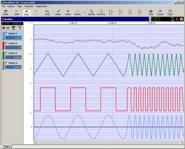
RealView 2.0
RealView is a measurement application, which records and plots measured values from analogue hardware devices in real-time. Several curves can be plotted into a single diagram. Several diagrams can be arranged on one or more pages if necessary. Plot options...
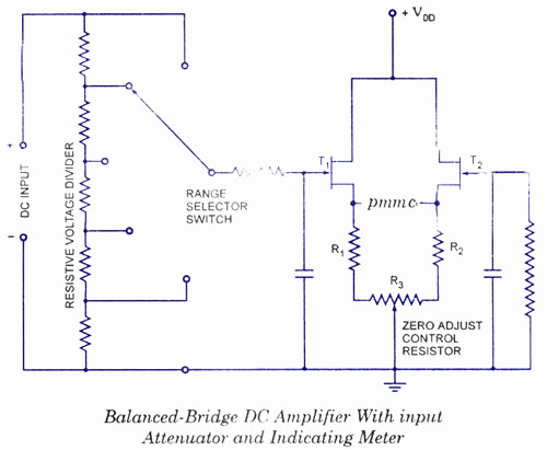
Electronic Multimeters
The electronic multimeter is a versatile general-purpose instrument capable of measuring both DC and AC voltages, as well as current and resistance. This solid-state device typically includes a built-in power supply for operation on AC mains and often features one...

Full Wave Rectifier Circuit with Averaging Filter
This circuit is an RMS-calibrated AC voltmeter that provides average readings. Removing capacitor C2 eliminates the averaging function, resulting in a precision full-wave rectifier, while removing capacitor C1 transforms the circuit into an absolute value generator. The operation of the...

µCurrent Adaptor for multimeters
The µCurrent is in many cases also able to improve upon your meters current range accuracy by using your meters more accurate mVDC or mVAC voltage ranges instead to display the DC or AC current. With AC the frequency response...