


RF Preamplifier Operating in Band 2 VHF Range
#VHF
#amplifier
#Band 2
#88-108 MHz
#RF
#preamplifier
#frequency range
#radio
#signal boost
#tuned circuit

Description: The circuit design utilizes a VHF amplifier configured to operate within the frequency range of 88 to 108 MHz, specifically for Band 2 radio applications.
The VHF amplifier circuit is designed to enhance weak radio frequency signals in the specified frequency band, which is commonly used for FM radio transmission. The amplifier typically consists of several key components, including transistors, resistors, capacitors, and possibly inductors, depending on the specific design requirements.
The transistors used in the amplifier are selected for their ability to operate efficiently at VHF frequencies. They may be configured in a common emitter or common collector arrangement to provide the desired gain while maintaining stability across the frequency range. Biasing resistors are employed to set the operating point of the transistors, ensuring linear amplification and minimizing distortion.
Capacitors are used for coupling and bypassing purposes. Coupling capacitors allow the AC signals to pass through while blocking DC components, and bypass capacitors help to stabilize the power supply by shunting high-frequency noise to ground. Inductors may be included in the design to form tuned circuits that enhance selectivity and improve the overall performance of the amplifier.
The circuit may also incorporate feedback mechanisms to enhance linearity and reduce gain variations due to temperature changes or component tolerances. The output stage of the amplifier is designed to match the impedance of the antenna or subsequent stages in the signal chain, ensuring maximum power transfer and minimizing signal loss.
Overall, the VHF amplifier circuit for Band 2 radio applications is a critical component in achieving clear and reliable radio signal reception and transmission within the designated frequency range. Proper design considerations, including component selection and circuit topology, are essential for optimizing performance and ensuring compliance with regulatory standards.The circuit design employs a VHF amplifier adjusted in such a way that it will operate in the frequency range of 88 to 108 MHz, as part of the Band 2 Radi..
The VHF amplifier circuit is designed to enhance weak radio frequency signals in the specified frequency band, which is commonly used for FM radio transmission. The amplifier typically consists of several key components, including transistors, resistors, capacitors, and possibly inductors, depending on the specific design requirements.
The transistors used in the amplifier are selected for their ability to operate efficiently at VHF frequencies. They may be configured in a common emitter or common collector arrangement to provide the desired gain while maintaining stability across the frequency range. Biasing resistors are employed to set the operating point of the transistors, ensuring linear amplification and minimizing distortion.
Capacitors are used for coupling and bypassing purposes. Coupling capacitors allow the AC signals to pass through while blocking DC components, and bypass capacitors help to stabilize the power supply by shunting high-frequency noise to ground. Inductors may be included in the design to form tuned circuits that enhance selectivity and improve the overall performance of the amplifier.
The circuit may also incorporate feedback mechanisms to enhance linearity and reduce gain variations due to temperature changes or component tolerances. The output stage of the amplifier is designed to match the impedance of the antenna or subsequent stages in the signal chain, ensuring maximum power transfer and minimizing signal loss.
Overall, the VHF amplifier circuit for Band 2 radio applications is a critical component in achieving clear and reliable radio signal reception and transmission within the designated frequency range. Proper design considerations, including component selection and circuit topology, are essential for optimizing performance and ensuring compliance with regulatory standards.The circuit design employs a VHF amplifier adjusted in such a way that it will operate in the frequency range of 88 to 108 MHz, as part of the Band 2 Radi..
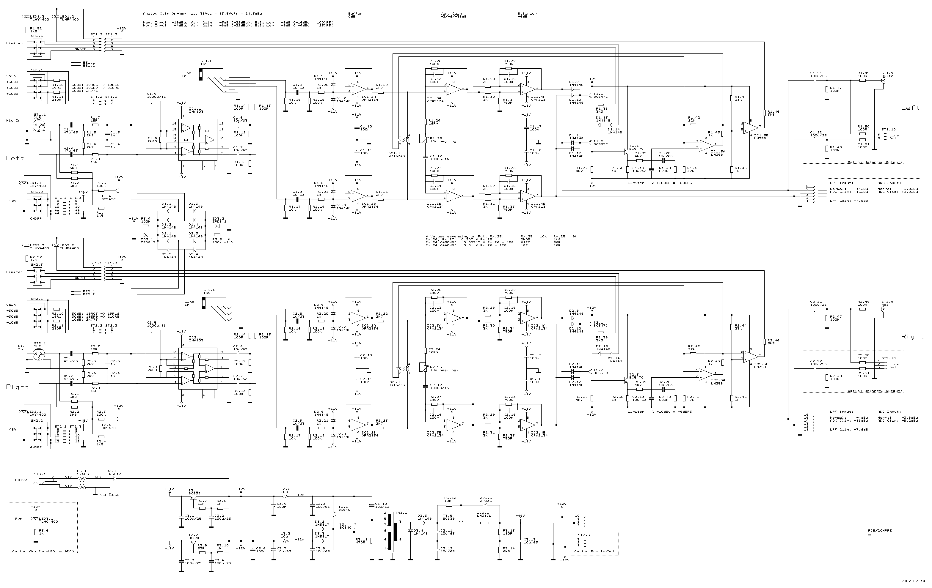
2ChPre
A dual-channel audio preamplifier designed to be an optimal preamplifier for the high-quality Audio Analog to Digital Converter AD24QS. The aim was not to create a smaller or cheaper preamplifier with similar functionality, but rather to develop a superior product....

Audio preamplifier circuits
The circuit described is straightforward yet efficient in its operation. The transistor Tr1 is utilized in a grounded base mode, with an input directed to its emitter to facilitate a low impedance input. The circuit is designed to operate effectively...
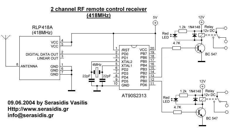
2 channel RF remote control
The basic small-range remote controls are Infrared and RF (Radio Frequency). One of the weaknesses of Infrared is that the signal cannot pass through walls. Therefore, to control a garage door, an RF remote control is necessary. The circuit (transmitter...

Fully adjustable preamplifier
This circuit is an audio preamplifier that has balance, tone, and loudness controls. It should be suitable as an example of good design for audio applications.
The audio preamplifier circuit utilizes the BAA730 and NE540 integrated circuits, which are key...

GBPPR 1 GHz RF Spectrum Analyzer
An RF spectrum analyzer is an essential tool for experimenters. The spectrum analyzer project described here is an enhancement of the "Spectrum Analyzer for the Radio Amateur" (Part 2) project by Wes Hayward (W7ZOI) and Terry White (K7TAU), which appeared...

MAX2620 10mhz To 1050mhz Integrated Rf Oscillator With Buffered Outputs
The MAX2620 integrates a low-noise oscillator with two output buffers in a cost-effective, plastic surface-mount, ultra-small uMAX package. This device combines functions that are typically achieved with discrete components.
The MAX2620 is designed for applications requiring precise frequency generation with minimal...

vhf antenna amplifier
The PCB of this circuit should be positioned close to the antenna within a compact metallic enclosure. This VHF antenna circuit requires a 12 volts DC power supply, which can be sourced from a 12-volt battery, as the current consumption...

4-18Mhz-converter
The unit consists of an RF amplifier Q1, a local oscillator Q2, and a mixer Q3. The two frequency bands are covered without a band switch by utilizing an intermediate frequency (IF) of 3.5 MHz. The oscillator operates within a...

Rf power meter
The reflectometer (SWR power meter) operates across three decades, ranging from 100 kHz to 100 MHz. It can be designed to handle RF power levels as low as 500 mW and up to 500 watts.
The reflectometer, also known as a...