


RF Probe and Watt Meter
#RF probe
#watt meter
#HF
#UHF
#coaxial cables
#RF voltage
#oscillators
#transistors
#power measurement

Description: This RF probe is designed for use at High Frequency (HF) or Ultra High Frequency (UHF) with both 50 and 75 ohm coaxial cables. It can measure RF voltage under both load and no-load conditions, enabling it to function as an RF wattmeter. The probe is suitable for oscillators and small transistors with power levels up to 2 Watts. The circuit operates as a simple half-wave rectifier, converting RF signals into a DC voltage. A single pole, double throw switch (S1) allows for the selection of a resistive load to be switched in or out of the circuit. The center position of S1 indicates no load, while the left and right positions correspond to 50 and 75 ohm measurements.
The RF probe also facilitates measuring RF voltage, current, and power. While digital and analog multimeters can measure AC voltages, they are limited to a specific frequency range for accurate readings. For instance, a Maplin meter accurately measures frequencies up to 400Hz with 1% accuracy and up to 20KHz with 4% accuracy, provided the waveform is a sine wave. Beyond 20KHz, accuracy diminishes. A simple diode detector circuit suffices for measuring radio frequencies. The probe utilizes an OA91 germanium diode, which is preferred over silicon diodes due to its lower forward voltage drop of approximately 0.2V, compared to silicon's 0.6-0.7V. The diode rectifies the RF signal into a DC voltage that can be accurately read by a multimeter. A 1nF capacitor smooths the rectified DC signal presented to the meter.
When measuring AC or RF signals, the currents and voltages are in phase only with a purely resistive load. Transmitters are typically tested with a resistive dummy load, simplifying calculations. For example, a 1-watt transmitter delivers an average power of 1 watt into a 50-ohm resistive dummy load. The power (P) is measured in RMS or root-mean-square terms, with the relationship given by P = V²/R. Rearranging this equation provides V(rms) = sqrt(P x R). Power can also be expressed as P = I²R, leading to I(rms) = (P/R). Peak values are approximately 1.414 times the RMS values. Switch S1 allows for the selection of either a 50 or 75 ohm resistive load, enabling the probe to measure both loaded and no-load voltages. Given the fixed resistance of the load, the power delivered to it can be calculated.
The RF probe is capable of measuring output impedance of a transmitter by taking two readings: one unloaded and one under load at either 50 or 75 ohms. The output power measured by the probe may differ from the actual radiated power by the antenna due to losses in the antenna system and the Standing Wave Ratio (SWR). When the antenna and feedline impedances do not match, some electrical energy is lost in the system.
The RF probe provides four primary functions. In all cases, it should be connected between the circuit under test and the meter, which may include a transmitter, RF oscillator, or other signal source. Since the OA91 diode and the 10n capacitor form a half-wave rectifier, the RF value measured will reflect a peak value. To measure a transmitter voltage under load, S1 should be positioned to either the 50 or 75 ohm setting, with 50 ohm being the standard, while the 75 ohm setting is recommended for Band II (87.5MHz - 108MHz). For determining the output impedance of an unknown circuit or transmitter, both unloaded and loaded readings must be taken. The output impedance can then be calculated using the appropriate equations.This RF probe can be used at High Frequency (HF) or Ultra High Frequency (UHF) on both 50 and 75 ohm coaxial cables. In addition the RF voltage can be measured under load or no-load conditions which allows the circuit to double as an RF Watt meter.
The RF probe can be used for oscillators and small transistors for powers up to 2 Watts. The circuit is a simple half wave rectifier. In this circuit it works at radio frequencies (RF) and converts any RF signal to a DC voltage, in addition S1, allows a resistive load to be switched in or out of circuit. S1 is a single pole, double throw switch with a Centre off position. The centre position is no load, and left and right positions 1 are for 50 and 75 ohm measurements. First, a small section on measuring RF voltage, current and power, then I`ll describe how to use this simple test instrument.
Digital and analogue multi meters can already measure AC voltages so why can`t they be used at radio frequencies The reason is that they can only measure with accuracy a limited frequency range. My Maplin meter measures frequencies up to 400Hz with 1% accuracy, and up to 20KHz at 4%. This also requires that the waveform is a sine wave. At frequencies above 20KHz, accuracy is not reliable. To measure radio frequencies (RF) a simple diode detector circuit is all that`s needed. The detector in this probe is an OA91 germanium diode, but any germanium diode will work. Germanium diodes have a low forward voltage drop (about 0. 2V) and are preferred to silicon diodes which have a higher (0. 6 - 0. 7V) voltage drop. The diode rectifies the RF signal and converts it to a DC voltage, which can be read by a multimeter with good accuracy; the 1nF capacitor is there to smooth the rectified DC signal presented to the meter.
When measuring any AC or RF signal, the currents and voltages are only in phase if the load is purely resistive. All transmitters are tested with a dummy load which are resistive. This simplifies the calculations and the pie chart for Ohms`s Law at AC can now be used. For example, a 1 watt transmitter delivers an average power of 1 watt into a 50-ohm resistive dummy load.
Transmitter power is measured in RMS or root-mean-square. As power, P = V2/R, then re-arranging, V(rms) = sqrt(P x R). Power is also found from P = I2R and re-arranging in terms of current, I(rms) = (P / R) Peak values are simply 1. 414 x the RMS values. S1 allows a 50 or 75 ohm resistive load to be switched in and out of circuit. This allows the probe to read loaded and no-load voltages. However as the load has a fixed resistance (50 or 75 ohm) then power delivered to the load can also be worked out.
Finally because the probe has a fixed resistance and can measure loaded and no-load voltages then it is possible to measure output impedance of a transmitter, see also Measuring Input and Output Impedance may also be of assistance. The RF probe has four functions: In all cases, connect the RF probe between the circuit under test and the meter.
The circuit under test could be a transmitter, RF oscillator or other signal source. As the OA91 diode and 10n capacitor are a half wave rectifier, the RF value measured will be a peak value. As V(RMS) = V(peak) / 2 then: To measure a transmitter voltage under load switch S1 to either 50 or 75 ohm position.
Normally this will be 50ohm, but for Band II ( 87. 5MHz - 108MHz) 75 ohm impedance should be used. To measure the output impedance of an unknown circuit or transmitter you first need to take two readings, one unloaded and then a reading under load at either 50 or 75 ohms. The output impedance can be found from the following equation: The output power as measured by the probe will not be exactly the same as the radiated power by the antenna.
This is because there are losses in the antenna system and the Standing Wave Ratio (SWR). When an antenna and feedline do not have matching impedances, some of the electrical energy
The RF probe also facilitates measuring RF voltage, current, and power. While digital and analog multimeters can measure AC voltages, they are limited to a specific frequency range for accurate readings. For instance, a Maplin meter accurately measures frequencies up to 400Hz with 1% accuracy and up to 20KHz with 4% accuracy, provided the waveform is a sine wave. Beyond 20KHz, accuracy diminishes. A simple diode detector circuit suffices for measuring radio frequencies. The probe utilizes an OA91 germanium diode, which is preferred over silicon diodes due to its lower forward voltage drop of approximately 0.2V, compared to silicon's 0.6-0.7V. The diode rectifies the RF signal into a DC voltage that can be accurately read by a multimeter. A 1nF capacitor smooths the rectified DC signal presented to the meter.
When measuring AC or RF signals, the currents and voltages are in phase only with a purely resistive load. Transmitters are typically tested with a resistive dummy load, simplifying calculations. For example, a 1-watt transmitter delivers an average power of 1 watt into a 50-ohm resistive dummy load. The power (P) is measured in RMS or root-mean-square terms, with the relationship given by P = V²/R. Rearranging this equation provides V(rms) = sqrt(P x R). Power can also be expressed as P = I²R, leading to I(rms) = (P/R). Peak values are approximately 1.414 times the RMS values. Switch S1 allows for the selection of either a 50 or 75 ohm resistive load, enabling the probe to measure both loaded and no-load voltages. Given the fixed resistance of the load, the power delivered to it can be calculated.
The RF probe is capable of measuring output impedance of a transmitter by taking two readings: one unloaded and one under load at either 50 or 75 ohms. The output power measured by the probe may differ from the actual radiated power by the antenna due to losses in the antenna system and the Standing Wave Ratio (SWR). When the antenna and feedline impedances do not match, some electrical energy is lost in the system.
The RF probe provides four primary functions. In all cases, it should be connected between the circuit under test and the meter, which may include a transmitter, RF oscillator, or other signal source. Since the OA91 diode and the 10n capacitor form a half-wave rectifier, the RF value measured will reflect a peak value. To measure a transmitter voltage under load, S1 should be positioned to either the 50 or 75 ohm setting, with 50 ohm being the standard, while the 75 ohm setting is recommended for Band II (87.5MHz - 108MHz). For determining the output impedance of an unknown circuit or transmitter, both unloaded and loaded readings must be taken. The output impedance can then be calculated using the appropriate equations.This RF probe can be used at High Frequency (HF) or Ultra High Frequency (UHF) on both 50 and 75 ohm coaxial cables. In addition the RF voltage can be measured under load or no-load conditions which allows the circuit to double as an RF Watt meter.
The RF probe can be used for oscillators and small transistors for powers up to 2 Watts. The circuit is a simple half wave rectifier. In this circuit it works at radio frequencies (RF) and converts any RF signal to a DC voltage, in addition S1, allows a resistive load to be switched in or out of circuit. S1 is a single pole, double throw switch with a Centre off position. The centre position is no load, and left and right positions 1 are for 50 and 75 ohm measurements. First, a small section on measuring RF voltage, current and power, then I`ll describe how to use this simple test instrument.
Digital and analogue multi meters can already measure AC voltages so why can`t they be used at radio frequencies The reason is that they can only measure with accuracy a limited frequency range. My Maplin meter measures frequencies up to 400Hz with 1% accuracy, and up to 20KHz at 4%. This also requires that the waveform is a sine wave. At frequencies above 20KHz, accuracy is not reliable. To measure radio frequencies (RF) a simple diode detector circuit is all that`s needed. The detector in this probe is an OA91 germanium diode, but any germanium diode will work. Germanium diodes have a low forward voltage drop (about 0. 2V) and are preferred to silicon diodes which have a higher (0. 6 - 0. 7V) voltage drop. The diode rectifies the RF signal and converts it to a DC voltage, which can be read by a multimeter with good accuracy; the 1nF capacitor is there to smooth the rectified DC signal presented to the meter.
When measuring any AC or RF signal, the currents and voltages are only in phase if the load is purely resistive. All transmitters are tested with a dummy load which are resistive. This simplifies the calculations and the pie chart for Ohms`s Law at AC can now be used. For example, a 1 watt transmitter delivers an average power of 1 watt into a 50-ohm resistive dummy load.
Transmitter power is measured in RMS or root-mean-square. As power, P = V2/R, then re-arranging, V(rms) = sqrt(P x R). Power is also found from P = I2R and re-arranging in terms of current, I(rms) = (P / R) Peak values are simply 1. 414 x the RMS values. S1 allows a 50 or 75 ohm resistive load to be switched in and out of circuit. This allows the probe to read loaded and no-load voltages. However as the load has a fixed resistance (50 or 75 ohm) then power delivered to the load can also be worked out.
Finally because the probe has a fixed resistance and can measure loaded and no-load voltages then it is possible to measure output impedance of a transmitter, see also Measuring Input and Output Impedance may also be of assistance. The RF probe has four functions: In all cases, connect the RF probe between the circuit under test and the meter.
The circuit under test could be a transmitter, RF oscillator or other signal source. As the OA91 diode and 10n capacitor are a half wave rectifier, the RF value measured will be a peak value. As V(RMS) = V(peak) / 2 then: To measure a transmitter voltage under load switch S1 to either 50 or 75 ohm position.
Normally this will be 50ohm, but for Band II ( 87. 5MHz - 108MHz) 75 ohm impedance should be used. To measure the output impedance of an unknown circuit or transmitter you first need to take two readings, one unloaded and then a reading under load at either 50 or 75 ohms. The output impedance can be found from the following equation: The output power as measured by the probe will not be exactly the same as the radiated power by the antenna.
This is because there are losses in the antenna system and the Standing Wave Ratio (SWR). When an antenna and feedline do not have matching impedances, some of the electrical energy
Simple UHF Video Transmitter
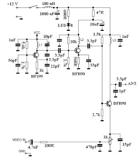
This video transmitter circuit operates on the UHF channel frequency of 470-580 MHz, specifically channels 21-34. It can transmit video signals over distances ranging from 30 to 100 meters when using a cable length of 10 to 20 cm. For...

UHF amplifying circuit diagram
The circuit depicted in the figure operates within a frequency range of 400 to 850 MHz, designed as a UHF amplifying circuit. For optimal performance and results, it is recommended that the circuit be manufactured using silver-tin processing techniques.
The UHF...

Uhf Motion Detector
The UHF motion detector operates on the Doppler radar principle. Q1 is an oscillator that creates a radiated signal. An object in the radiated field reflects some of this energy back to the detector. If the object is moving, the...

intercom circuit with transistors
The key to avoiding instability (motor-boating) in a high-gain circuit is to power the speaker using a separate power supply. This circuit design allows for the connection of one or two additional stations. It is recommended to construct the circuit...

uhf tv pre amplifier
This is another UHF-TV preamplifier circuit diagram that is simpler than the previous UHF TV preamplifier. This circuit is based on the MPSH10 transistor. Alternatives that can be used to replace the MPSH10 include the BF180 and BCY90. The tuned...

TA1326FNG UHF Band RF Modulator IC For VTRs
The TA1383AFG integrates an NTSC chroma decoder, a multi-point scan sync processor (equivalent to pin D4), and an H/V frequency counter in a 30-pin flat package. This integrated circuit (IC) is suitable for double scan televisions manufactured by Toshiba Semiconductor.
The...

ATA5760 ATA5760 UHF ASK/FSK Receiver
The ATA6823 is designed specifically for automotive applications that require high-power motors. It provides four high-current gate driver outputs capable of driving a wide range of n-channel power MOSFETs in a full-bridge configuration. A fully integrated charge pump with external...

rf probe circuit
Comprehensive information about RF Probe Circuits is available. Users can learn about and download RF Probe Circuit designs online.
RF Probe Circuits are essential tools for testing and analyzing radio frequency signals in various applications, including telecommunications, broadcasting, and electronic testing....

UHF Audio Video Sender Circuit
This audio-video circuit enables wireless audio and visual transmission to a television. The television functions as a receiver, eliminating the necessity for a separate monitor. It can also be connected to a VCR or CCD camera, and can be configured...