


Self-powered cw monitor

Description: Position L near the transmitter output tank to hear the key-down tone. Then secure the coil in place. C = 47 µF, R = 8 kΩ, Q = HEP 253 (or equivalent), T = 500: 500 ohm center-tapped transformer. More: L = 2 to 6 turns on a 2-inch coil form.
The circuit described involves a resonant tank circuit typically used in RF (radio frequency) applications. The inductor (L) should be positioned close to the output of the transmitter, allowing the operator to hear the key-down tone, which confirms that the transmitter is active. The inductor is to be securely fastened in place, ensuring stability and consistent performance during operation.
The capacitor (C) is specified as 47 microfarads (µF), which plays a crucial role in filtering and stabilizing the voltage within the circuit, contributing to the overall performance of the RF signal. The resistor (R) has a value of 8 kilohms (kΩ), which is likely used for biasing or limiting current in the circuit, ensuring that the components operate within safe parameters.
The transistor (Q) specified is a HEP 253 or an equivalent component, which functions as a switching element in the circuit, allowing for modulation of the RF signal. The center-tapped transformer (T) with a 500:500 ohm specification is essential for impedance matching between the transmitter and the load, optimizing power transfer and signal clarity.
The inductor (L) is constructed with 2 to 6 turns of wire wound on a 2-inch coil form. The number of turns will affect the inductance value, which is critical for tuning the circuit to the desired frequency, ensuring that the transmitter operates efficiently and effectively. Proper attention must be paid to the winding technique and the physical placement of the coil to minimize losses and maximize performance.
This configuration allows for effective modulation and transmission of RF signals, making it suitable for various applications in amateur radio, communication systems, and other electronic projects where RF transmission is required.Position L near the transmitter output tank to hear the key-down tone. Then tape the coil in place. C = 47 µf, R = 8 K, Q = HEP 253 (or equal), T = 500: 500 ohm center tapped transformer L = 2 to 6 turns on V2" coil form.
The circuit described involves a resonant tank circuit typically used in RF (radio frequency) applications. The inductor (L) should be positioned close to the output of the transmitter, allowing the operator to hear the key-down tone, which confirms that the transmitter is active. The inductor is to be securely fastened in place, ensuring stability and consistent performance during operation.
The capacitor (C) is specified as 47 microfarads (µF), which plays a crucial role in filtering and stabilizing the voltage within the circuit, contributing to the overall performance of the RF signal. The resistor (R) has a value of 8 kilohms (kΩ), which is likely used for biasing or limiting current in the circuit, ensuring that the components operate within safe parameters.
The transistor (Q) specified is a HEP 253 or an equivalent component, which functions as a switching element in the circuit, allowing for modulation of the RF signal. The center-tapped transformer (T) with a 500:500 ohm specification is essential for impedance matching between the transmitter and the load, optimizing power transfer and signal clarity.
The inductor (L) is constructed with 2 to 6 turns of wire wound on a 2-inch coil form. The number of turns will affect the inductance value, which is critical for tuning the circuit to the desired frequency, ensuring that the transmitter operates efficiently and effectively. Proper attention must be paid to the winding technique and the physical placement of the coil to minimize losses and maximize performance.
This configuration allows for effective modulation and transmission of RF signals, making it suitable for various applications in amateur radio, communication systems, and other electronic projects where RF transmission is required.Position L near the transmitter output tank to hear the key-down tone. Then tape the coil in place. C = 47 µf, R = 8 K, Q = HEP 253 (or equal), T = 500: 500 ohm center tapped transformer L = 2 to 6 turns on V2" coil form.

simple self-powered circuit
This simple circuit is started running by connecting a twelve volt battery across the terminals, causing the large diameter Light-Emitting Diode to light up. When the battery is removed, the LED stays lit up because the circuit has become self-powering....

Precision tandem type power supply circuit diagram
The circuit depicted features a secondary N3 center tap transformer (T) with a common point connecting diodes VD2 and VD3 to positive electrodes, along with capacitors C2, C6, C7, and negative electrodes connected to capacitors C9 and C10. Additional components...

remote control circuit
The remote control circuit comprises two main components: a transmitter and a receiver. The transmitter circuit is controlled by an NE555 integrated circuit (IC), while the receiver operates based on the frequency of the signal emitted by the transmitter. It...

50W Tube-Valve SW transmitter
This transmitter operates in the shortwave range from 6 MHz to 22 MHz. Coil L1 serves as the shortwave oscillating coil for the 6SA7 vacuum tube and is commercially available. Capacitor C1 is a variable capacitor with a capacitance range...

Sputnik QSO Party Transmitter Prototype
This document describes a prototype transmitter for the Sputnik QSO Party. The RF output power is 450 mW, with 70 V DC at 14.4 mA on the V2 anode. The screen current (G2) for V2 is 1.6 mA, while the...
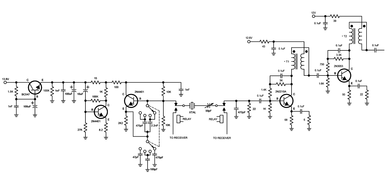
Deluxe Crystal Controlled Transmitter
A high-quality QRP transmitter, named NEXUS 6, is designed to explore issues related to extremely narrow bandwidth communication. This device is not merely a simplified version of a QRP transmitter; it aims to create a cost-effective system that can be...

Transmitter Negative Key Line Keyer
Using an NTE288 (or ECG288, GE223, or SK3434), this circuit can key a negative line up to -300 V maximum. Do not use this circuit to key a vacuum-tube amplifier that draws grid current because the keying transistor might be...
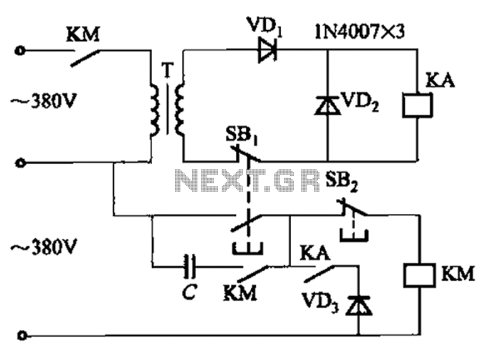
Transformer AC contactor DC operation circuit b
The AC contactor DC transformer circuit operates using various types of transformers and AC contactors in a DC application.
The AC contactor DC transformer circuit is designed to control and manage electrical power in applications where alternating current (AC) is converted...

wireless headphones transmitter
This wireless headphone transmitter ensures a reliable connection over a distance of 2 meters. The oscillator frequency ranges between 1750 KHz and 3500 KHz, utilizing a ferrite bar as the antenna. IC1 amplifies the audio signal, while TC1 serves as...