


Simple CB receiver with SO42P
#CB receiver
#27MHz
#RF circuit
#SO42P
#inductor tuning
#loudspeaker
#transmitter
#aerial
#potentiometer


Description: For the regulation needs a transmitter or generator in mpa'nta the CB, that is to say in the region 27MHz. If you have a certain friend with CB, you convince you to help. Connect a piece of cable around in the one metre in the place of aerial. Be supplied the receptor with + 12V and turn in half the potentiometer of regulation of sound (R12). Turn on the generator or the transmitter CB and you emit in distance of 10 metres roughly from the receptor, in the channel that receives the receptor. From the loudspeaker it will be supposed it begins to be heard what you emit and if it does not have big force, you turn the core of inductor L1/L2 until you have a increase of intensity. After this you can continue with the various medium frequencies beginning from black (MF3) until you have the biggest intensity. If it is heard mjkrofwnjsmo's, you lower little the intensity of loudspeaker or you remove the transmitter from the receptor. More: If you cannot find krysta'lloys you can make the modification that shows the form. That is to say, instead of crystal you in joint action put respectively coordinated circuits with LC each one in different channel. The receptor this can combine itself with the transmitter CB in order to you manufacture a complete station CB.
The circuit described is for a CB (Citizens Band) radio transmitter and receiver setup operating at a frequency of approximately 27 MHz. The primary components include a transmitter or generator, a receiver, a loudspeaker, and an inductor (L1/L2). The setup requires a 12V power supply for the receiver, which is essential for its operation. The regulation of sound is achieved through a potentiometer (R12) that allows for volume adjustment.
To set up the system, a piece of approximately one meter of cable is used as an antenna. Once the antenna is connected, the transmitter or generator is powered on, and the user is advised to emit signals from a distance of about 10 meters from the receiver. The receiver should be tuned to the same channel as the transmitter to ensure proper communication.
If the initial signal strength is insufficient, the core of the inductor (L1/L2) can be adjusted to increase the intensity of the received signal. The user can then explore different medium frequencies, starting from a specified frequency (MF3), to find the optimal setting for the strongest signal reception.
In cases where specific components, such as crystals (referred to as "krysta'lloys"), are unavailable, it is possible to modify the circuit. Instead of using a crystal, LC circuits can be employed, each tuned to a different channel, allowing for flexibility in the design. The receiver can be designed to work in conjunction with the CB transmitter, forming a complete CB station capable of two-way communication. This configuration is suitable for amateur radio enthusiasts and can be tailored to specific needs based on available components and desired functionality.For the regulation needs a transmitter or generator in mpa'nta the CB, that is to say in the region 27MHz. If you have a certain friend with CB, you convince you to help. Connect a piece of cable around in the one metre in the place of aerial. Be supplied the receptor with + 12V and turn in half the potentiometer of regulation of sound (R12). Turn on the generator or the transmitter CB and you emit in distance of 10 metres roughly from the receptor, in the channel that receives the receptor.
From the loudspeaker it will be supposed it begins to be heard what you emit and if it does not have big force, you turn the core of inductor L1/L2 until you have a increase of intensity. After this you can continue with the various medium frequencies beginning from black (MF3) until you have the biggest intensity.
If it is heard mjkrofwnjsmo's, you lower little the intensity of loudspeaker or you remove the transmitter from the receptor. If you cannot find krysta'lloys you can make the modification that shows the form. That is to say, instead of crystal you in joint action put respectively coordinated circuits with LC each one in different channel. The receptor this can combine itself with the transmitter CB in order to you manufacture a complete station CB.
The circuit described is for a CB (Citizens Band) radio transmitter and receiver setup operating at a frequency of approximately 27 MHz. The primary components include a transmitter or generator, a receiver, a loudspeaker, and an inductor (L1/L2). The setup requires a 12V power supply for the receiver, which is essential for its operation. The regulation of sound is achieved through a potentiometer (R12) that allows for volume adjustment.
To set up the system, a piece of approximately one meter of cable is used as an antenna. Once the antenna is connected, the transmitter or generator is powered on, and the user is advised to emit signals from a distance of about 10 meters from the receiver. The receiver should be tuned to the same channel as the transmitter to ensure proper communication.
If the initial signal strength is insufficient, the core of the inductor (L1/L2) can be adjusted to increase the intensity of the received signal. The user can then explore different medium frequencies, starting from a specified frequency (MF3), to find the optimal setting for the strongest signal reception.
In cases where specific components, such as crystals (referred to as "krysta'lloys"), are unavailable, it is possible to modify the circuit. Instead of using a crystal, LC circuits can be employed, each tuned to a different channel, allowing for flexibility in the design. The receiver can be designed to work in conjunction with the CB transmitter, forming a complete CB station capable of two-way communication. This configuration is suitable for amateur radio enthusiasts and can be tailored to specific needs based on available components and desired functionality.For the regulation needs a transmitter or generator in mpa'nta the CB, that is to say in the region 27MHz. If you have a certain friend with CB, you convince you to help. Connect a piece of cable around in the one metre in the place of aerial. Be supplied the receptor with + 12V and turn in half the potentiometer of regulation of sound (R12). Turn on the generator or the transmitter CB and you emit in distance of 10 metres roughly from the receptor, in the channel that receives the receptor.
From the loudspeaker it will be supposed it begins to be heard what you emit and if it does not have big force, you turn the core of inductor L1/L2 until you have a increase of intensity. After this you can continue with the various medium frequencies beginning from black (MF3) until you have the biggest intensity.
If it is heard mjkrofwnjsmo's, you lower little the intensity of loudspeaker or you remove the transmitter from the receptor. If you cannot find krysta'lloys you can make the modification that shows the form. That is to say, instead of crystal you in joint action put respectively coordinated circuits with LC each one in different channel. The receptor this can combine itself with the transmitter CB in order to you manufacture a complete station CB.

simple tv audio video transmitter
A simple TV audio-video transmitter circuit can be constructed using this schematic diagram. This circuit allows for the transmission of video signals from a VCR or other devices to a TV without the need for cables. The video signals input...

Two way Loudspeaker cross-over
The resistance of loudspeakers is characterized in a frequency depending on the destination and their press. Loudspeakers are distinguished, as for the destination, in loudspeakers of low frequencies, woofer intermediate, mid-range and high tweeter. Their resistance in Ω is 4Ω,...

TA8136S Radio Control Transmitter Ic - Toshiba Semiconductor
TB6556FG is a 3-phase full-wave sine-wave PWM brushless motor controller. It features sine-wave PWM control and includes a built-in triangular-wave generator with a carrier cycle defined as fosc/252 (Hz). The device also offers a built-in lead angle control function that...

Test Transmitter
The Test Transmitter (A3020) is a combination of three circuits designed to test the Subcutaneous Transmitter (A3019) and to analyze surface acoustic wave (SAW) voltage-controlled oscillators (VCOs). The A3020 incorporates the complete A3019 circuit in its central section, which closely...

Wireless Transmitter
A basic circuit of the transistor UHF radio transmitter with a surface acoustic wave resonator (SAW) is presented. The SAW is utilized as a positive feedback element connected between the transistor's base and an LC network in parallel. In this...

Electronics/Transmitter design
For a fixed frequency transmitter, a common method is to use a resonant quartz crystal in a crystal oscillator to establish the frequency. In transmitters where the frequency must be variable, several options are available. It is often the case...

Emergency Egg Locator Beacon (EELB)
This project was inspired by a circuit that a friend, Simon Field, showcased. He built a simple transmitter circuit using a 1 MHz "can" oscillator and a serial connector. In his circuit, he utilized a computer to turn the transmitter...

Interfaces For The Remote-Control Transmitter Circuit
Several possible interface circuits are presented for use with a remote-control transmitter. The circuit labeled A demonstrates a typical FM stereo MUX decoder with a load connected directly to the open-collector output of a TA7343 PLL. The circuit labeled B...
Remote tuning transmitter
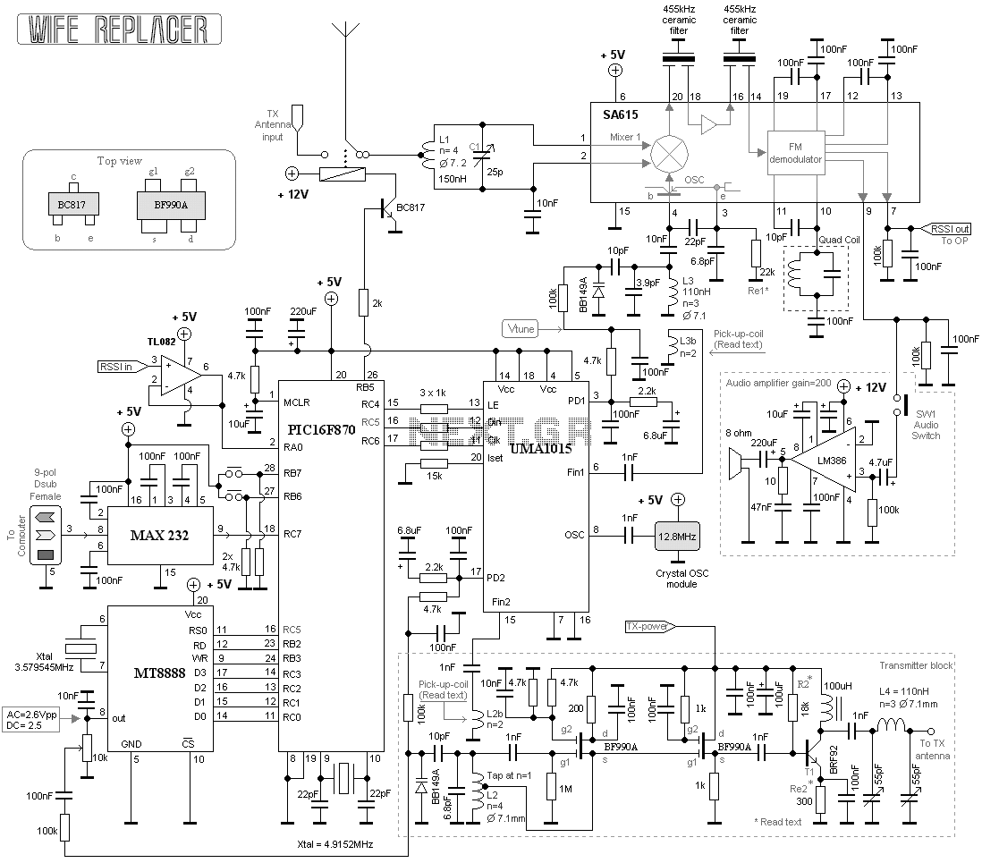
This project consists of a wide range receiver and one transmitter. Together they will form a unit which will help you tuning your homebrewed transmitter. The most difficult part of homebrewing is the tuning part of the transmitters. How should...