


Simple FM Modulator Design
#FM modulator
#transmitter
#oscillator
#RF
#frequency modulation
#wireless
#communication
#signal processing
#broadcast
#electronics
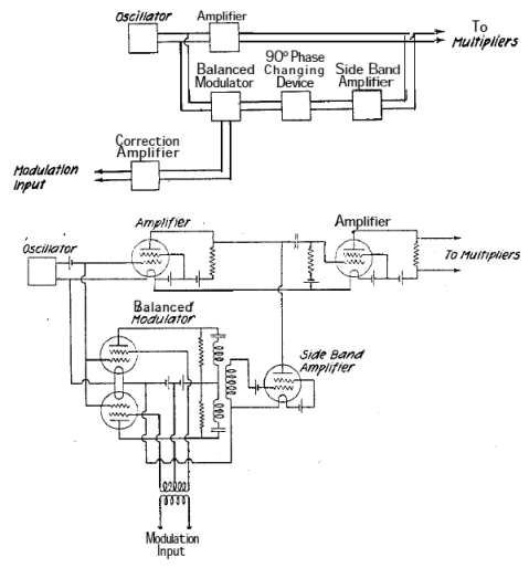
Description: A system is being developed to transmit in the FM band. The oscillators have already been constructed to facilitate transmission across multiple frequencies.
The design of an FM transmission system involves several key components, including oscillators, modulators, amplifiers, and antennas. The oscillators, which have already been constructed, are crucial as they generate the carrier signals at specific frequencies within the FM band, typically ranging from 88 MHz to 108 MHz.
To achieve multi-frequency transmission, a frequency synthesizer may be employed, allowing for precise tuning and stability across the desired frequency range. This can be accomplished using phase-locked loops (PLLs) or direct digital synthesis (DDS) techniques, which provide flexibility in frequency selection and modulation.
The modulation stage is essential for encoding the audio or data signal onto the carrier wave. This is typically achieved using a voltage-controlled oscillator (VCO) that varies its frequency based on the amplitude of the input audio signal, effectively creating frequency modulation. The modulated signal is then amplified using RF amplifiers to ensure adequate power for transmission.
The final stage involves the antenna, which must be designed to efficiently radiate the modulated signal into the surrounding environment. The choice of antenna type (e.g., dipole, monopole, or loop) will depend on the desired range and coverage area of the transmission.
Careful consideration must also be given to compliance with regulatory standards governing FM transmissions to avoid interference with other services and ensure proper licensing. Power levels, frequency stability, and bandwidth must all adhere to the relevant guidelines to maintain operational integrity and legality.
Overall, the successful implementation of an FM transmission system requires meticulous design and integration of these components to achieve reliable and high-quality signal transmission.Hello, I want to build a system that can transmit in the FM band. I have already built my oscillators because I want to transmit at more than one..
The design of an FM transmission system involves several key components, including oscillators, modulators, amplifiers, and antennas. The oscillators, which have already been constructed, are crucial as they generate the carrier signals at specific frequencies within the FM band, typically ranging from 88 MHz to 108 MHz.
To achieve multi-frequency transmission, a frequency synthesizer may be employed, allowing for precise tuning and stability across the desired frequency range. This can be accomplished using phase-locked loops (PLLs) or direct digital synthesis (DDS) techniques, which provide flexibility in frequency selection and modulation.
The modulation stage is essential for encoding the audio or data signal onto the carrier wave. This is typically achieved using a voltage-controlled oscillator (VCO) that varies its frequency based on the amplitude of the input audio signal, effectively creating frequency modulation. The modulated signal is then amplified using RF amplifiers to ensure adequate power for transmission.
The final stage involves the antenna, which must be designed to efficiently radiate the modulated signal into the surrounding environment. The choice of antenna type (e.g., dipole, monopole, or loop) will depend on the desired range and coverage area of the transmission.
Careful consideration must also be given to compliance with regulatory standards governing FM transmissions to avoid interference with other services and ensure proper licensing. Power levels, frequency stability, and bandwidth must all adhere to the relevant guidelines to maintain operational integrity and legality.
Overall, the successful implementation of an FM transmission system requires meticulous design and integration of these components to achieve reliable and high-quality signal transmission.Hello, I want to build a system that can transmit in the FM band. I have already built my oscillators because I want to transmit at more than one..

Wireless two-tone electronic doorbell circuit diagram
The transmitter circuit is activated by pressing the SB button. Components D1, D2, R2, R3, and C4 form a low-frequency oscillator that controls an audio oscillator made up of D3, D4, D5, and D6, allowing them to operate alternately. The...

Oscillator-clock generator
This self-starting fixed frequency oscillator circuit provides excellent frequency stability. R1 and C1 form the frequency-determining network, while R2 supplies regenerative feedback. Diode D1 improves stability by compensating for the difference between Voh and Vsupply. In applications requiring a precision...

Garage door open indicator
There are battery-powered wireless systems available, but the ones encountered would indicate that the door was open even if it was left ajar for ventilation. A system was desired that would alert when the door was fully raised. Additionally, it...
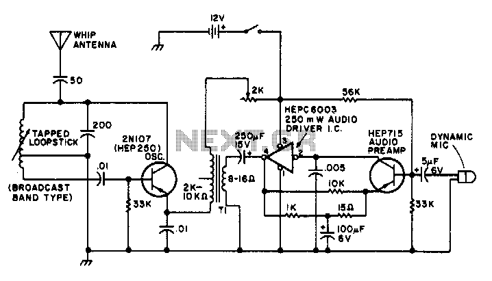
1-2Mhz broadcast transmitter
T1 is a low impedance output transformer with a conversion ratio of 5000 to 8 ohms.
The low impedance output transformer, T1, is designed to match the output of an audio amplifier to the impedance of the speaker load. The specified...

Wireless doorbell 300MHz
The operation of a 303MHz circuit has been covered in our project WIRELESS DOORBELL. We are not going over how the circuit works but explain the importance of some of the components and how they affect the range. The most...

Circuit of power fm transmitter transistor 2n2218 audio wireless 1KM
This small transmitter can reach distances of more than 1 km under favorable transmission conditions. Modulation can be achieved using a microphone, such as an electret microphone, or another audio source. The transmitter includes a coil made of 5 turns...
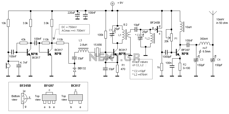
50MHz crystal bug
This bugg is based on my previous 3-transistor transmitter. This bugg unit has many advantages. The transmitter uses a crystal 46.515MHz to hold a steady frequency. The frequency can be fine-tuned by some 100kHz. The transmitter can send data and...
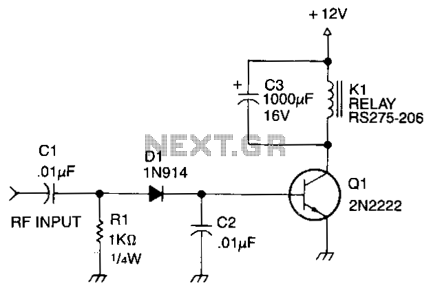
Rf-actuated-relay
Automatic antenna switching or RF power indication can be achieved with this circuit. Relay will key with less than 150 mW drive on 2 m.
The circuit designed for automatic antenna switching or RF power indication utilizes a relay that is...

RF Inductance adaptor for multimeter
The circuit's operating principle is that if you make a pulse width proportional to inductance, and keep the pulse frequency and amplitude constant, and then pass the pulse through a low pass filter so that only the average voltage comes...