


Stage VI Mixer
#DSP
#local oscillator
#signal source
#center frequency
#transceiver
#MHz
#kHz
#dummy load
#coupling

Description: In the "DSP" tab's "Local Oscillator" section, click on the button labeled "Single Band" and enter the desired center frequency (7046000). This configures Rocky's center frequency to 7.046 MHz. Set up the transceiver or another signal source to transmit a low-power signal at 7.059 KHz into a dummy load, loosely coupling it to the board with a short wire. If the signal source can sweep the frequency, observe Rocky's spectrum display as the generator sweeps through the bandwidth chunk centered on the center frequency. Inject an RF signal of approximately 10 mV RMS at the ANT and RTN pads located on the right side of the main board. The signal should be a few kHz on either side of the selected center frequency (for instance, inject a 7.059 MHz signal for a center frequency of 7.046 MHz). Check the output at the R (ring) and T (tip) pads on the left side of the main board. The output should be an audio frequency that represents the difference between the injected signal and the selected center frequency, approximately 5 V p-p. Once the mixer tests are completed and the additional hardware is installed, the radio is ready for operation. This final test will utilize Rocky as the SDR software. This test assumes the following:
The described setup involves configuring a Software Defined Radio (SDR) system, specifically using the Rocky software to analyze signals. The process begins by adjusting the local oscillator frequency to the desired center frequency of 7.046 MHz. This is a critical step, as the local oscillator frequency determines the operational bandwidth and the range of frequencies the SDR can effectively process.
Once the local oscillator is set, the next step involves preparing a signal source. A low-power signal at 7.059 KHz is generated and transmitted into a dummy load. The purpose of using a dummy load is to prevent signal reflection and ensure that the test environment is controlled. The signal source should be loosely coupled to the board with a short wire, allowing for minimal interference while still enabling signal injection.
For the spectrum analysis, the signal source can be programmed to sweep frequencies around the center frequency. This sweeping action allows for a visual representation of the signal spectrum on Rocky's display, facilitating the identification of signal characteristics and any potential interference within the specified bandwidth.
The RF signal injection at the ANT and RTN pads is a crucial phase in the testing process. By injecting a signal of about 10 mV RMS, the system can assess how well the SDR processes the input signal. The selected frequency for injection should be close to the center frequency, ensuring that the output reflects the intended audio frequency difference. The output at the R and T pads should yield an audio frequency signal of approximately 5 V p-p, indicating successful signal processing by the SDR.
Completion of the mixer tests and installation of any additional hardware marks the transition to practical operation. The final test phase, utilizing Rocky as the SDR software, confirms that the system is functioning correctly and is capable of receiving and processing signals as intended. This comprehensive setup and testing procedure ensures that the SDR is fully operational and ready for real-world applications.In the "DSP" tab`s "Local Oscillator" section, click on the button marked "Single Band" and type in the desired center frequency (7046000). This sets Rocky`s center frequency at 7. 046 MHz. Set up your transceiver (or other signal source) to transmit a low power signal at 7. 059 KHz into a dummy load and loosely couple it to the board with a short wire If your signal source can sweep the frequency, observe Rocky`s spectrum display as the generator sweeps through the "chunk" of bandwidth centered on the center frequency. Inject an RF signal of about 10 mV RMS at the ANT and RTN pads on the right side on the main board. The signal should be a few kHz either side of the selected center frequency (e. g. , inject a 7. 059 MHz signal for a center frequency of 7. 046 MHz. Look for the output at the R (ring) and T (tip) pads on the left side of the main board. It should be an audio frequency representing the difference between the injected signal and the selected center frequency and it should be approximately 5 V p-p.
Once the mixer tests are completed and the extra hardware is installed, you are ready to take the radio for a spin. This final test will use Rocky as the SDR Software. This test assumes you have the following:
The described setup involves configuring a Software Defined Radio (SDR) system, specifically using the Rocky software to analyze signals. The process begins by adjusting the local oscillator frequency to the desired center frequency of 7.046 MHz. This is a critical step, as the local oscillator frequency determines the operational bandwidth and the range of frequencies the SDR can effectively process.
Once the local oscillator is set, the next step involves preparing a signal source. A low-power signal at 7.059 KHz is generated and transmitted into a dummy load. The purpose of using a dummy load is to prevent signal reflection and ensure that the test environment is controlled. The signal source should be loosely coupled to the board with a short wire, allowing for minimal interference while still enabling signal injection.
For the spectrum analysis, the signal source can be programmed to sweep frequencies around the center frequency. This sweeping action allows for a visual representation of the signal spectrum on Rocky's display, facilitating the identification of signal characteristics and any potential interference within the specified bandwidth.
The RF signal injection at the ANT and RTN pads is a crucial phase in the testing process. By injecting a signal of about 10 mV RMS, the system can assess how well the SDR processes the input signal. The selected frequency for injection should be close to the center frequency, ensuring that the output reflects the intended audio frequency difference. The output at the R and T pads should yield an audio frequency signal of approximately 5 V p-p, indicating successful signal processing by the SDR.
Completion of the mixer tests and installation of any additional hardware marks the transition to practical operation. The final test phase, utilizing Rocky as the SDR software, confirms that the system is functioning correctly and is capable of receiving and processing signals as intended. This comprehensive setup and testing procedure ensures that the SDR is fully operational and ready for real-world applications.In the "DSP" tab`s "Local Oscillator" section, click on the button marked "Single Band" and type in the desired center frequency (7046000). This sets Rocky`s center frequency at 7. 046 MHz. Set up your transceiver (or other signal source) to transmit a low power signal at 7. 059 KHz into a dummy load and loosely couple it to the board with a short wire If your signal source can sweep the frequency, observe Rocky`s spectrum display as the generator sweeps through the "chunk" of bandwidth centered on the center frequency. Inject an RF signal of about 10 mV RMS at the ANT and RTN pads on the right side on the main board. The signal should be a few kHz either side of the selected center frequency (e. g. , inject a 7. 059 MHz signal for a center frequency of 7. 046 MHz. Look for the output at the R (ring) and T (tip) pads on the left side of the main board. It should be an audio frequency representing the difference between the injected signal and the selected center frequency and it should be approximately 5 V p-p.
Once the mixer tests are completed and the extra hardware is installed, you are ready to take the radio for a spin. This final test will use Rocky as the SDR Software. This test assumes you have the following:

DSP Mixed Signal Solutions for Multi Channel Audio
The limitation of this architecture is that it overlooks the variations among different channels. Initially, the subwoofer channel has a limited bandwidth, and its signal is often produced in real-time by summing the low-frequency components from the full-bandwidth channels. Additionally,...

80 METER CW TRANSCEIVER WITH DIRECT CONVERSION
The RF signal is divided into two signals that are shifted 90 degrees out of phase (one at plus 45 degrees and one at minus 45 degrees). Both signals are then mixed to audio frequencies. The two audio signals are...

A 70cm Wide-band Transceiver Concept
This article provides a detailed overview of a 70 cm wideband transceiver designed for duplex operation. The modules operate within a 200 kHz wide duplex channel, selectable from 430-440 MHz with a 100 kHz channel spacing. Initial prototypes were introduced...

Motorola DSP Receiver
Ralph Stirling, KC3F, and another engineer developed the first generation of a digital signal processing (DSP) system using the Texas Instruments C5X DSK starter kit. The second generation represents a significant advancement, utilizing the more appropriate Motorola DSP56002EVM evaluation board....
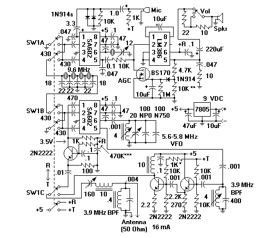
75 meter qrp ssb transceiver
The transceiver switches the four-element 1500-ohm crystal band-pass filter (BPF) connections between the inputs and outputs of two SA602 integrated circuits to reverse the signal flow for receive/transmit (R/T) operation. Since no intermediate frequency (IF) amplifier is utilized in this...

N5ESEs QRP Dummy Load With Built-in RF Detector
This is a variation of the "parallel resistor" dummy load. It is designed for QRP HF operation of 5 watts or less average power and is suitable for continuous operation at that level. The dummy load is compact, measuring approximately...

Icom IC-751 (IC 751 IC751) transceiver mods reviews software and diagrams
The 751 required turning the volume control almost to the 12 o'clock position before achieving any noticeable volume, which raised concerns about potential issues. To address this, all electrolytic capacitors associated with the audio path, specifically after the detector stage...

40 meters CW Transceiver
This project describes a little QRP transceiver full legal power (5 W at 12 V) for the 40 meters band. The RIG may be built in a gradual manner; in fact, it is divided into two main modules, or you...

GenesisRadio Transceivers
Later, the same pivot table will be utilized to list the parts for each of the eight phases in the build, organizing them into phase-specific bags of parts. The initial observation is that there are slight inconsistencies between the well-illustrated...