


Stereo Encoder for FM transmitters
#stereo encoder
#FM transmitter
#microcontroller
#analogue processing
#digital processing
#high-quality
#sampling frequency
#pilot tone
#spectral residues

Description: This stereo encoder is a halfway between analogue and digital processing. It combines the best from both domains to provide high-quality and easy to build device. The sampling frequency used in this stereo encoder is 97 times higher than the pilot tone frequency. This makes it very easy to reject all spectral residues around the sampling frequency without affecting the main signal characteristics. The use of a microcontroller allows for building this stereo encoder with a reduced part count and achieving excellent results in real operation. This stereo encoder does not contain any preemphasis circuit. A compressor/limiter/clipper device must always be present between the preemphasis circuit and the stereo encoder or modulator. This configuration ensures loud sound without exceeding the maximum frequency deviation limit (75 kHz). The stereo encoder is designed to provide really good sound. The compressor/limiter/clipper device should be used where the preemphasis is precisely assured. The Pira CZ Compressor/Limiter/Clipper is highly suitable for this task.
Characteristics:
Signal overshooting prevention (overshooting max. 10%)
Low noise and distortion
No adjustment (only pilot tone level and output level)
High channel separation and spectral purity in common operation
RDS input and pilot sync output makes it easy to connect any RDS encoder
Microcomputer controlled, hex file provided for free
All parts are easy to buy (including crystal)
Supply voltage: 9-16 V (stabilized)
Quiescent supply current (12 V): 34 mA
Audio 19 kHz rejection: 40 dB
Channel separation at 1 kHz: >55 dB
Subcarrier rejection: >60 dB
Pilot sampling frequency: 1.843 MHz (19 kHz x 97)
Subcarrier sampling frequency: 1.843 MHz (38 kHz x 48.5)
Pilot sync output: TTL
Max audio input voltage: 5 V pp (1.75 V rms)
Pilot tone level: linear adjustable 0-0.5 V pp
Output voltage gain: linear adjustable 0-1.5
Audio input impedance: 2000 ohm
RDS input impedance: 1000 ohm
MPX output impedance: 500 ohm
Pilot sync output impedance: 10000 ohm
Signal-to-noise ratio: >70 dB
Part list:
U1-U3 - TLC272, TS272
U4, U5 - 74HC4053 (74HCT4053)
U6 - 7805
U7 - PIC18F1220-I/P with stereo.hex file inside
Y1 - Crystal 7.3728 MHz (7.372 MHz)
SW1 - Button
L1, L2 - Coil 15 mH (09P-153J)
RN1, RN2 - SIL resistor network 3x 1k (discrete, 6 pin)
C1, C2 - 47p (C)
C3, C4, C5, C9, C24, C33-C35 C37 - 100n (C)
C6 - 82p (C)
C7, C19, C20, C30, C31 - 270p (C)
C8, C11, C14, C22, C23 - 220u/10V (E)
C10, C21, C25, C32 - 560p (C)
C12, C36, C38, C39 - 100u/10V (E)
C13 - 470u/25V (E)
C15, C26, C40 - 22p (C)
C16, C27 - 2n7 (P)
C17, C28 - 4n7 (P, 5%)
C18, C29 - 10n (C)
R1, R24 - 20k (1%)
R2-R9, R30, R31, R38, R39, R49, R50 - 2k (1%)
R10 - 160k
R11 - 330k
R12, R16, R27-R29, R40-R42 - 39k
R13 - 82k
R14, R17, R18, R20, R21, R25, R32, R43 - 10k (1%)
R15, R26 - 1k
R19 - 470R
R33, R34, R44, R45 - 30k (1%)
R35, R46 - 16k (1%)
R36, R47 - 47R
R37, R48 - 680R
R22, R23 - Trimmer 5k
The stereo encoder circuit described integrates both analog and digital processing techniques to achieve high-quality audio encoding. The core of this design utilizes a microcontroller (PIC18F1220-I/P) to manage the encoding process, allowing for efficient control and reduced component count. The use of a high sampling frequency, specifically 1.843 MHz, ensures that unwanted spectral residues are effectively filtered out, preserving the integrity of the audio signal.
The circuit's architecture includes several operational amplifiers (TLC272, TS272) that handle signal conditioning and amplification. The 74HC4053 multiplexers are utilized for switching between different signal paths, enhancing the versatility of the encoder. Voltage regulation is provided by the 7805, ensuring stable operation across the specified supply voltage range of 9-16 V.
Key performance characteristics include a signal-to-noise ratio exceeding 70 dB, channel separation greater than 55 dB at 1 kHz, and low distortion levels, making this encoder suitable for professional audio applications. The design also incorporates a robust compressor/limiter/clipper stage, essential for maintaining audio fidelity while adhering to maximum frequency deviation limits.
The inclusion of RDS input and pilot sync output facilitates easy integration with RDS encoders, broadening the application scope of the encoder. The adjustable pilot tone level and output voltage gain allow for fine-tuning of the audio output to meet specific requirements.
Overall, this stereo encoder is a well-rounded solution for audio encoding, combining the reliability of analog processing with the precision of digital control, making it an excellent choice for various broadcasting and audio transmission applications.This stereo encoder is a halfway between analogue and digital processing. It combines the best from both domains to provide high-quality and easy to build device. The sampling frequency used in this stereo encoder is 97 times (!!!) higher than the pilot tone frequency. This makes very easy to reject all spectral residues around the sampling frequency without affecting the main signal characteristics.
Using of a microcontroller allows to build this stereo encoder with reduced part count and get excellent results in real operation. This stereo encoder advisedly does not contain any preemphasis circuit. Remember the key fact: a compressor/limiter/clipper device must be always present between the preemphasis circuit and the stereo encoder or modulator. Only this configuration ensures loud sound without exceeding the maximum frequency deviation limit (75 kHz).
The stereo encoder is designed to provide really good sound. This always needs to use the compressor/limiter/clipper device where the preemphasis is precisely assured. The Pira CZ Compressor/Limiter/Clipper is highly suitable for this task. Characteristics: Signal overshooting prevention (overshooting max. 10 %) Low noise and distortion No adjust (only pilot tone level and output level) High channel separation and spectral purity in common operation RDS input and pilot sync.
output makes easy to connect any RDS encoder Microcomputer controlled, hex file provided for free All parts are easy to buy (incl. crystal) Supply voltage: 9-16 V (stabilized) Quiescent supply current (12 V): 34 mA Audio 19 kHz rejection: 40 dB Channel separation at 1 kHz: >55 dB Subcarrier rejection: >60 dB Pilot sampling frequency: 1.843 MHz (19 kHz x 97) Subcarrier sampling frequency: 1.843 MHz (38 kHz x 48.5) Pilot sync.
output: TTL Max. audio input voltage: 5 V pp (1.75 V rms) Pilot tone level: linear adjustable 0-0.5 V pp Output voltage gain: linear adjustable 0-1.5 Audio input impedance: 2000 ohm RDS input impedance: 1000 ohm MPX output impedance: 500 ohm Pilot sync. output impedance: 10000 ohm Signal-to-noise ratio: >70 dB Part list: U1-U3 - TLC272, TS272 U4, U5 - 74HC4053 (74HCT4053) U6 - 7805 U7 - PIC18F1220-I/P with stereo.hex file inside Y1 - Crystal 7.3728 MHz (7.372 MHz) SW1 - Button L1, L2 - Coil 15 mH (09P-153J) RN1, RN2 - SIL resistor network 3x 1k (discrete, 6 pin) C1, C2 - 47p (C) C3, C4, C5, C9, C24, C33-C35 C37 - 100n (C) C6 - 82p (C) C7, C19, C20, C30, C31 - 270p (C) C8, C11, C14, C22, C23 - 220u/10V (E) C10, C21, C25, C32 - 560p (C) C12, C36, C38, C39 - 100u/10V (E) C13 - 470u/25V (E) C15, C26, C40 - 22p (C) C16, C27 - 2n7 (P) C17, C28 - 4n7 (P, 5%) C18, C29 - 10n (C) R1, R24 - 20k (1%) R2-R9, R30, R31, R38, R39, R49, R50 - 2k (1%) R10 - 160k R11 - 330k R12, R16, R27-R29, R40-R42 - 39k R13 - 82k R14, R17, R18, R20, R21, R25, R32, R43 - 10k (1%) R15, R26 - 1k R19 - 470R R33, R34, R44, R45 - 30k (1%) R35, R46 - 16k (1%) R36, R47 - 47R R37, R48 - 680R R22, R23 - Trimmer 5k
Characteristics:
Signal overshooting prevention (overshooting max. 10%)
Low noise and distortion
No adjustment (only pilot tone level and output level)
High channel separation and spectral purity in common operation
RDS input and pilot sync output makes it easy to connect any RDS encoder
Microcomputer controlled, hex file provided for free
All parts are easy to buy (including crystal)
Supply voltage: 9-16 V (stabilized)
Quiescent supply current (12 V): 34 mA
Audio 19 kHz rejection: 40 dB
Channel separation at 1 kHz: >55 dB
Subcarrier rejection: >60 dB
Pilot sampling frequency: 1.843 MHz (19 kHz x 97)
Subcarrier sampling frequency: 1.843 MHz (38 kHz x 48.5)
Pilot sync output: TTL
Max audio input voltage: 5 V pp (1.75 V rms)
Pilot tone level: linear adjustable 0-0.5 V pp
Output voltage gain: linear adjustable 0-1.5
Audio input impedance: 2000 ohm
RDS input impedance: 1000 ohm
MPX output impedance: 500 ohm
Pilot sync output impedance: 10000 ohm
Signal-to-noise ratio: >70 dB
Part list:
U1-U3 - TLC272, TS272
U4, U5 - 74HC4053 (74HCT4053)
U6 - 7805
U7 - PIC18F1220-I/P with stereo.hex file inside
Y1 - Crystal 7.3728 MHz (7.372 MHz)
SW1 - Button
L1, L2 - Coil 15 mH (09P-153J)
RN1, RN2 - SIL resistor network 3x 1k (discrete, 6 pin)
C1, C2 - 47p (C)
C3, C4, C5, C9, C24, C33-C35 C37 - 100n (C)
C6 - 82p (C)
C7, C19, C20, C30, C31 - 270p (C)
C8, C11, C14, C22, C23 - 220u/10V (E)
C10, C21, C25, C32 - 560p (C)
C12, C36, C38, C39 - 100u/10V (E)
C13 - 470u/25V (E)
C15, C26, C40 - 22p (C)
C16, C27 - 2n7 (P)
C17, C28 - 4n7 (P, 5%)
C18, C29 - 10n (C)
R1, R24 - 20k (1%)
R2-R9, R30, R31, R38, R39, R49, R50 - 2k (1%)
R10 - 160k
R11 - 330k
R12, R16, R27-R29, R40-R42 - 39k
R13 - 82k
R14, R17, R18, R20, R21, R25, R32, R43 - 10k (1%)
R15, R26 - 1k
R19 - 470R
R33, R34, R44, R45 - 30k (1%)
R35, R46 - 16k (1%)
R36, R47 - 47R
R37, R48 - 680R
R22, R23 - Trimmer 5k
The stereo encoder circuit described integrates both analog and digital processing techniques to achieve high-quality audio encoding. The core of this design utilizes a microcontroller (PIC18F1220-I/P) to manage the encoding process, allowing for efficient control and reduced component count. The use of a high sampling frequency, specifically 1.843 MHz, ensures that unwanted spectral residues are effectively filtered out, preserving the integrity of the audio signal.
The circuit's architecture includes several operational amplifiers (TLC272, TS272) that handle signal conditioning and amplification. The 74HC4053 multiplexers are utilized for switching between different signal paths, enhancing the versatility of the encoder. Voltage regulation is provided by the 7805, ensuring stable operation across the specified supply voltage range of 9-16 V.
Key performance characteristics include a signal-to-noise ratio exceeding 70 dB, channel separation greater than 55 dB at 1 kHz, and low distortion levels, making this encoder suitable for professional audio applications. The design also incorporates a robust compressor/limiter/clipper stage, essential for maintaining audio fidelity while adhering to maximum frequency deviation limits.
The inclusion of RDS input and pilot sync output facilitates easy integration with RDS encoders, broadening the application scope of the encoder. The adjustable pilot tone level and output voltage gain allow for fine-tuning of the audio output to meet specific requirements.
Overall, this stereo encoder is a well-rounded solution for audio encoding, combining the reliability of analog processing with the precision of digital control, making it an excellent choice for various broadcasting and audio transmission applications.This stereo encoder is a halfway between analogue and digital processing. It combines the best from both domains to provide high-quality and easy to build device. The sampling frequency used in this stereo encoder is 97 times (!!!) higher than the pilot tone frequency. This makes very easy to reject all spectral residues around the sampling frequency without affecting the main signal characteristics.
Using of a microcontroller allows to build this stereo encoder with reduced part count and get excellent results in real operation. This stereo encoder advisedly does not contain any preemphasis circuit. Remember the key fact: a compressor/limiter/clipper device must be always present between the preemphasis circuit and the stereo encoder or modulator. Only this configuration ensures loud sound without exceeding the maximum frequency deviation limit (75 kHz).
The stereo encoder is designed to provide really good sound. This always needs to use the compressor/limiter/clipper device where the preemphasis is precisely assured. The Pira CZ Compressor/Limiter/Clipper is highly suitable for this task. Characteristics: Signal overshooting prevention (overshooting max. 10 %) Low noise and distortion No adjust (only pilot tone level and output level) High channel separation and spectral purity in common operation RDS input and pilot sync.
output makes easy to connect any RDS encoder Microcomputer controlled, hex file provided for free All parts are easy to buy (incl. crystal) Supply voltage: 9-16 V (stabilized) Quiescent supply current (12 V): 34 mA Audio 19 kHz rejection: 40 dB Channel separation at 1 kHz: >55 dB Subcarrier rejection: >60 dB Pilot sampling frequency: 1.843 MHz (19 kHz x 97) Subcarrier sampling frequency: 1.843 MHz (38 kHz x 48.5) Pilot sync.
output: TTL Max. audio input voltage: 5 V pp (1.75 V rms) Pilot tone level: linear adjustable 0-0.5 V pp Output voltage gain: linear adjustable 0-1.5 Audio input impedance: 2000 ohm RDS input impedance: 1000 ohm MPX output impedance: 500 ohm Pilot sync. output impedance: 10000 ohm Signal-to-noise ratio: >70 dB Part list: U1-U3 - TLC272, TS272 U4, U5 - 74HC4053 (74HCT4053) U6 - 7805 U7 - PIC18F1220-I/P with stereo.hex file inside Y1 - Crystal 7.3728 MHz (7.372 MHz) SW1 - Button L1, L2 - Coil 15 mH (09P-153J) RN1, RN2 - SIL resistor network 3x 1k (discrete, 6 pin) C1, C2 - 47p (C) C3, C4, C5, C9, C24, C33-C35 C37 - 100n (C) C6 - 82p (C) C7, C19, C20, C30, C31 - 270p (C) C8, C11, C14, C22, C23 - 220u/10V (E) C10, C21, C25, C32 - 560p (C) C12, C36, C38, C39 - 100u/10V (E) C13 - 470u/25V (E) C15, C26, C40 - 22p (C) C16, C27 - 2n7 (P) C17, C28 - 4n7 (P, 5%) C18, C29 - 10n (C) R1, R24 - 20k (1%) R2-R9, R30, R31, R38, R39, R49, R50 - 2k (1%) R10 - 160k R11 - 330k R12, R16, R27-R29, R40-R42 - 39k R13 - 82k R14, R17, R18, R20, R21, R25, R32, R43 - 10k (1%) R15, R26 - 1k R19 - 470R R33, R34, R44, R45 - 30k (1%) R35, R46 - 16k (1%) R36, R47 - 47R R37, R48 - 680R R22, R23 - Trimmer 5k

iPod FM transmiter
Electronics-DIY provides instructions for constructing a simple portable FM transmitter that enables an iPod to broadcast music over radio waves. The assembly is straightforward and can be housed within a mouse case. The device operates easily, featuring a power switch...

Transmitter FM 45W with valve
FM Transmitter 45W with valve. TECHNICAL CHARACTERISTICS: Power supply: 220V AC Frequency range: 88~108MHz Output power: max 45W.
The FM transmitter described operates within the frequency range of 88 to 108 MHz, which is the standard FM broadcasting band. It utilizes...
FM Transmission and Reception
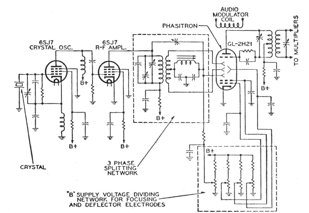
The original frequency modulation (FM) transmitters produced by the General Electric Company were of the direct FM type, utilizing a standard electronic automatic frequency control system similar to that associated with the CBS transmitter. The FM multiplication system in these...
IR On/Off Switch Using Microcontroller
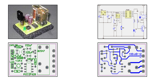
The ability to turn electrical devices ON or OFF using a remote control is a well-established concept, with numerous devices effectively performing this function.
To implement a remote control system for switching electrical devices, a typical schematic would include several key...

Four Stage FM Transmitter Circuit PCB
Here is the circuit diagram of a four RF stage FM transmitter. The stages include a very high frequency (VHF) oscillator built around the HF transistor BF494, a pre-amplifier using the BF200 transistor, a driver transistor 2N2219, and a power...

3w fm transmitter
This schematic represents an FM transmitter that delivers an output power of 3 to 3.5 watts, operational within the frequency range of 90 to 110 MHz. While the stability of the circuit is acceptable, incorporating a Phase-Locked Loop (PLL) can...

Electronic TIC TAC TOE
This project is not to introduce Tic Tac Toe. Everyone knows this game. It is to introduce two features: bi-coloured LEDs, microcontrollers, and the skill of writing an ALGORITHM. You can use the project to learn the skills of creating...

2 Transistor FM Voice Transmitter
Take care with transmitter circuits. It is illegal in most countries to operate radio transmitters without a license. Although only low power this circuit may be tuned to operate over the range 87-108MHz with a range of 20 or 30...

the simplest fm transmitter ever made
This is a simple and inexpensive FM transmitter. The circuit operates at a low voltage using a CR2025 3V battery with low current consumption. The total size of this FM transmitter, including the battery but excluding the antenna, is smaller...