


Tesla Coil Powerful Radio Transmitter with A Lousy Antenna
#Tesla Coil
#RF transmitter
#high power
#antenna
#radio frequency
#electrical engineering
#wireless transmission
#resonance
#electromagnetism
#experimental circuits
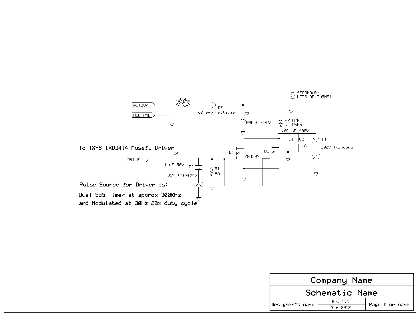
Description: A Tesla Coil can be understood as a high-power radio frequency transmitter with an inefficient antenna. The secondary coil functions as a significantly shortened quarter-wave antenna.
The Tesla Coil is an electrical resonant transformer circuit that is designed to produce high-voltage, low-current, high-frequency alternating current electricity. It consists of two main components: a primary coil and a secondary coil, which are coupled inductively. The primary coil is energized by a power source, typically a capacitor bank, which discharges through the coil, creating a magnetic field. This magnetic field induces a current in the secondary coil, where the voltage is stepped up significantly due to the turns ratio between the primary and secondary coils.
The secondary coil, which acts as a quarter-wave antenna, resonates at a specific frequency determined by its physical dimensions and the surrounding environment. This resonance allows the Tesla Coil to produce high-frequency oscillations, resulting in the generation of high-voltage discharges. The efficiency of the antenna, however, is limited, leading to a significant amount of energy being lost as radiation rather than being effectively transmitted.
In practical applications, Tesla Coils are often used for demonstrations in educational settings to illustrate principles of electromagnetic fields and resonance. They can also be utilized in various experimental setups, including wireless power transmission and high-voltage experiments. The design of a Tesla Coil requires careful consideration of components such as capacitors, spark gaps, and transformers to ensure safe operation and optimal performance.
Safety precautions are paramount when working with Tesla Coils due to the high voltages involved, which can pose serious risks. Proper grounding, insulation, and protective equipment are essential to mitigate hazards associated with electric shock and arc flash.I have tried to figure out what exactly a Tesla Coil was for years. I finally occurred to me that the best way to think of a Tesla Coil was as a very high power rf transmitter simply with a terrible antenna. The secondary is really just an ultra shortened 1/4 wave antenna.
The Tesla Coil is an electrical resonant transformer circuit that is designed to produce high-voltage, low-current, high-frequency alternating current electricity. It consists of two main components: a primary coil and a secondary coil, which are coupled inductively. The primary coil is energized by a power source, typically a capacitor bank, which discharges through the coil, creating a magnetic field. This magnetic field induces a current in the secondary coil, where the voltage is stepped up significantly due to the turns ratio between the primary and secondary coils.
The secondary coil, which acts as a quarter-wave antenna, resonates at a specific frequency determined by its physical dimensions and the surrounding environment. This resonance allows the Tesla Coil to produce high-frequency oscillations, resulting in the generation of high-voltage discharges. The efficiency of the antenna, however, is limited, leading to a significant amount of energy being lost as radiation rather than being effectively transmitted.
In practical applications, Tesla Coils are often used for demonstrations in educational settings to illustrate principles of electromagnetic fields and resonance. They can also be utilized in various experimental setups, including wireless power transmission and high-voltage experiments. The design of a Tesla Coil requires careful consideration of components such as capacitors, spark gaps, and transformers to ensure safe operation and optimal performance.
Safety precautions are paramount when working with Tesla Coils due to the high voltages involved, which can pose serious risks. Proper grounding, insulation, and protective equipment are essential to mitigate hazards associated with electric shock and arc flash.I have tried to figure out what exactly a Tesla Coil was for years. I finally occurred to me that the best way to think of a Tesla Coil was as a very high power rf transmitter simply with a terrible antenna. The secondary is really just an ultra shortened 1/4 wave antenna.

Simplest RF Transmitter
This is likely the simplest radio transmitter available. It comprises five components and can be assembled in a compact space. It is ideal for science fair projects or other science-related activities where short-range transmission is beneficial. The device operates on...

Brovin Kacher Tesla
"Cold electricity" refers to RF frequency alternating current (AC). In sinusoidal AC, the voltage is positive for half the cycle and negative for the other half. An oscilloscope can display this waveform, but a voltmeter may read zero because it...

TESLA COIL SECONDARY RECEIVER
Here is a Tesla coil secondary design: Wind 750 turns of 24-gauge enameled magnet wire onto an 18-inch long piece of 1.9-inch outer-diameter PVC pipe. The large coil has an inductance of approximately 2800 mH and a self-capacitance of about...

Solid-State Tesla Coil 2
Tesla constructed the world's most powerful radio transmitter. Surrounding the base of a 200-foot mast, he installed an air-core transformer that measured 75 feet in diameter. The primary winding consisted of only a few turns of wire, while the secondary...

RF transmitter uses AMI encoding
The circuit in Figure 2 shows a 16-channel, AMI-encoded RF transmitter for data rates as high as 28.8 kbps. The circuit operates in the unlicensed (FCC Part 15) 902- to 928-MHz industrial, scientific, and medical (ISM) band and is reliable...

Field circuit diagram of the needle
The antenna consists of approximately 20 cm of insulation made from strands, which are glued together inside a small plastic box. An RF current is processed through two diode rectifiers, and a 10k potentiometer is connected to the pin field....

200W Valve RF Transmitter circuit
This transmitter consists of three stages: the oscillator stage utilizing a 6L6 tube, the amplifier isolator stage with an 807 tube, and the final stage of the transmitter featuring an 811 tube. The coil L1 is specified by the market...

915-MHz antenna monopole
The Tab antenna is a folded monopole that you miniaturize by forming it into an inverted L with a downward bend at the end. You can solder it perpendicular to a pc board or build it as part of a...

High power control for sensitive contacts
Two simple arrangements for resistive loads are shown in A and B. The circuit in A will provide load power when the actuating contact is closed, and no power when the contact is open. B provides the reverse of this...