


Tracking Transmitter Circuit
#tracking transmitter
#multivibrator
#FM transmitter
#audio-tone generator
#transmit switch
#Ql
#Q2
#Q3
#Q4

Description: This tracking transmitter consists of four distinct subassemblies: a free-running multivibrator, a transmit switch, an audio-tone generator, and an FM transmitter. The multivibrator, which produces a pulse width with a pulse separation of 1500 ms, is built around Q1 and Q2. The multivibrator output is coupled through R5 to the base of Q3, whose emitter feeds Q4, which controls the circuit's transmitter section.
The tracking transmitter is a sophisticated device designed for precise signal transmission and tracking applications. It integrates four essential components that work together seamlessly.
The free-running multivibrator serves as the timing circuit, generating a continuous square wave signal characterized by a pulse width and a pulse separation of 1500 milliseconds. This is crucial for maintaining a stable output frequency, which is determined by the values of the resistors and capacitors used in the circuit. Transistors Q1 and Q2 are configured in a feedback loop to ensure oscillation, with their collector and emitter configurations carefully selected to achieve the desired pulse characteristics.
The output from the multivibrator is coupled to the base of transistor Q3 through resistor R5. This coupling serves to amplify the pulse signal generated by the multivibrator. Q3 functions as an intermediate amplifier, providing sufficient drive to transistor Q4. The emitter of Q3 is connected to the base of Q4, which acts as a switch to control the transmitter section of the circuit.
The transmit switch, which is part of the overall architecture, allows for the modulation of the signal for transmission. This section is responsible for turning the transmitter on and off as needed, ensuring efficient power usage and signal integrity.
The audio-tone generator produces a modulating tone that can be superimposed on the transmitted signal, enhancing the tracking capabilities of the transmitter. This audio tone can be adjusted based on the requirements of the tracking application.
Finally, the FM transmitter section is responsible for broadcasting the modulated signal over a specified frequency range. This section typically includes additional components such as an antenna and frequency-determining elements to ensure compliance with regulatory standards for transmission.
Overall, the design of this tracking transmitter emphasizes reliability and precision, making it suitable for various applications in tracking and monitoring systems. This tracking transmitter consists of four distinct subassemblies; a free-running multivibrator, a transmit switch, an audio-tone generator, and an FM transmitter. The multivibrator (which produces a pulse width with a pulse separation of 1500 ms) is built around Ql and Q2.
The multivibrator output is coupled through R5 to the base of Q3, whose emitter feeds Q4, which controls the circuit`s transmitter section.
The tracking transmitter is a sophisticated device designed for precise signal transmission and tracking applications. It integrates four essential components that work together seamlessly.
The free-running multivibrator serves as the timing circuit, generating a continuous square wave signal characterized by a pulse width and a pulse separation of 1500 milliseconds. This is crucial for maintaining a stable output frequency, which is determined by the values of the resistors and capacitors used in the circuit. Transistors Q1 and Q2 are configured in a feedback loop to ensure oscillation, with their collector and emitter configurations carefully selected to achieve the desired pulse characteristics.
The output from the multivibrator is coupled to the base of transistor Q3 through resistor R5. This coupling serves to amplify the pulse signal generated by the multivibrator. Q3 functions as an intermediate amplifier, providing sufficient drive to transistor Q4. The emitter of Q3 is connected to the base of Q4, which acts as a switch to control the transmitter section of the circuit.
The transmit switch, which is part of the overall architecture, allows for the modulation of the signal for transmission. This section is responsible for turning the transmitter on and off as needed, ensuring efficient power usage and signal integrity.
The audio-tone generator produces a modulating tone that can be superimposed on the transmitted signal, enhancing the tracking capabilities of the transmitter. This audio tone can be adjusted based on the requirements of the tracking application.
Finally, the FM transmitter section is responsible for broadcasting the modulated signal over a specified frequency range. This section typically includes additional components such as an antenna and frequency-determining elements to ensure compliance with regulatory standards for transmission.
Overall, the design of this tracking transmitter emphasizes reliability and precision, making it suitable for various applications in tracking and monitoring systems. This tracking transmitter consists of four distinct subassemblies; a free-running multivibrator, a transmit switch, an audio-tone generator, and an FM transmitter. The multivibrator (which produces a pulse width with a pulse separation of 1500 ms) is built around Ql and Q2.
The multivibrator output is coupled through R5 to the base of Q3, whose emitter feeds Q4, which controls the circuit`s transmitter section.

SMD FM Transmitter
Construct a low-power FM transmitter using surface-mount devices (SMD) that can be received by a standard FM radio. Soldering surface-mounted devices is relatively straightforward. Many small FM transmitter designs exist, but they often have issues. Firstly, an audio amplifier is...

Wireless FM Transmitter Circuit
The wireless FM transmitter circuit described here includes an additional RF power amplifier stage following the oscillator stage, which increases the power output to 200-250 mW.
The wireless FM transmitter circuit functions by modulating audio signals onto a radio frequency carrier...

Simple FM transmitter powered by 1.5V battery
This simple FM (frequency modulation) transmitter is powered only by a 1.5V battery and utilizes a single transistor. The frequency of this transmitter is controlled by the L-C resonance circuit and operates within a range of 80 to 110 MHz....

Low-power FM transmitter circuit diagram 1000M range
The components available were utilized to create a long-range FM radio transmitter operating within the 88-108 MHz band, designed for playing music. The circuit includes a power section that rectifies mains voltage to provide a stable 12V DC for the...
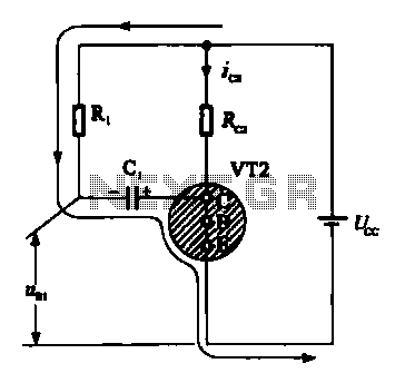
Multivibrator oscillation circuit
When VRI is off, 0 [2 is activated, allowing current to flow through RJ and Ci. When VT1 conducts, charging of C1 begins, causing it to discharge. This results in an inverting charge on C1, making the voltage positive, which...

LOW POWER FM TRANSMITTER
A low power FM pirate radio. The output power is approximately +35 dBm (3.16 watts) over a 50-ohm load and operates on a +24-volt power supply. The project consists of a Hartley oscillator (modulated VCO) and three stages (Class A,...

FM Transmitter circuit diagram (50M) With 2N2222 Transistor
This is an FM transmitter circuit diagram. This circuit uses a 2N2222 transistor, allowing it to operate at 3V and transmit signals up to 50 meters.
The FM transmitter circuit consists of several key components, primarily centered around the 2N2222 transistor,...

4 Stage FM transmitter circuit diagram
A four-stage FM transmitter circuit diagram utilizes four radio frequency stages: a VHF oscillator designed around the BF494 transistor (T1), a preamplifier based on the BF200 transistor (T2), a driver built with the 2N2219 transistor (T3), and a power amplifier...

Voyager MkII Page 1
This is one of the smallest and most compact FM transmitters available as a construction project, with the added benefit of being offered as a complete kit of parts. This convenience eliminates the need to source components from multiple suppliers,...