


Transmission indicator
#transmission indicator
#push-to-talk
#RF signal
#germanium diode
#SCR
#pilot lamp
#rectifier
#antenna
#transmitter

Description: Every time the push-to-talk button is closed, the light will turn on. The antenna samples the output RF from the transmitter. That signal is then rectified (detected) by germanium diode D1 and used to charge capacitor C2. The DC output is used to trigger a small silicon-controlled rectifier (SCR1), which allows the current to flow through the small pilot lamp. For lower-power applications, such as CB radio, the antenna must be closely coupled to the transmitter.
In this circuit design, the push-to-talk button functions as a momentary switch that initiates the operation of the system. When the button is pressed, it completes the circuit, allowing the RF signal from the transmitter to be sampled by the antenna. This RF signal is then directed to the germanium diode D1, which serves as a rectifier. The diode's role is crucial as it converts the alternating current (AC) RF signal into a direct current (DC) signal.
The rectified DC signal is then utilized to charge capacitor C2. This capacitor acts as a storage element, smoothing out any fluctuations in the DC signal and providing a stable voltage for subsequent components in the circuit. Once the voltage across C2 reaches a certain threshold, it triggers the silicon-controlled rectifier (SCR1). The SCR is a semiconductor device that acts as a switch, allowing current to flow through the pilot lamp once it is activated.
The pilot lamp serves as an indicator, illuminating when the SCR is conducting. This visual feedback is essential for the operator to know that the push-to-talk button is engaged and the transmitter is active. The design is particularly suitable for lower-power applications, such as CB radios, where the antenna must be closely coupled to the transmitter to ensure effective signal transmission and reception.
Overall, this circuit effectively combines RF sampling, signal rectification, energy storage, and visual indication, making it a practical solution for communication systems requiring a simple yet reliable push-to-talk functionality.Everytime the push-to-talk button is closed the light will go on. The antenna samples the output RF from the transmitter. That signal is then rectified (detected) by germanium diode Dl, and used to charge capacitor C2. The dc output is used to trigger a small silicon-controlled rectifier (SCR1), which permits the current to flow through the small pilot lamp. For lower-power applications, such as CB radio, the antenna will have to be close-coupled to the antenna.
In this circuit design, the push-to-talk button functions as a momentary switch that initiates the operation of the system. When the button is pressed, it completes the circuit, allowing the RF signal from the transmitter to be sampled by the antenna. This RF signal is then directed to the germanium diode D1, which serves as a rectifier. The diode's role is crucial as it converts the alternating current (AC) RF signal into a direct current (DC) signal.
The rectified DC signal is then utilized to charge capacitor C2. This capacitor acts as a storage element, smoothing out any fluctuations in the DC signal and providing a stable voltage for subsequent components in the circuit. Once the voltage across C2 reaches a certain threshold, it triggers the silicon-controlled rectifier (SCR1). The SCR is a semiconductor device that acts as a switch, allowing current to flow through the pilot lamp once it is activated.
The pilot lamp serves as an indicator, illuminating when the SCR is conducting. This visual feedback is essential for the operator to know that the push-to-talk button is engaged and the transmitter is active. The design is particularly suitable for lower-power applications, such as CB radios, where the antenna must be closely coupled to the transmitter to ensure effective signal transmission and reception.
Overall, this circuit effectively combines RF sampling, signal rectification, energy storage, and visual indication, making it a practical solution for communication systems requiring a simple yet reliable push-to-talk functionality.Everytime the push-to-talk button is closed the light will go on. The antenna samples the output RF from the transmitter. That signal is then rectified (detected) by germanium diode Dl, and used to charge capacitor C2. The dc output is used to trigger a small silicon-controlled rectifier (SCR1), which permits the current to flow through the small pilot lamp. For lower-power applications, such as CB radio, the antenna will have to be close-coupled to the antenna.

Arms single-phase rectifier bridge rectifier circuit
The circuit depicted is a single-phase bridge rectifier. It consists of arms with a cathode (negative electrode) and parallel anodes (positive electrodes) arranged in a configuration that connects multiple rectifier modules to form a bridge, commonly referred to as a...

Long Period SCR Timer
This is an SCR timer circuit. In this circuit, an SCR is utilized to activate the final actuator, which is a buzzer. The time constant of the circuit is determined by resistor R1 and capacitor C1. The buzzer will sound...

Antenna Booster for FM AM and SW Receiver
This AM/FM antenna booster circuit amplifies the broadband signal from the antenna. This antenna booster is designed to work for FM, AM, and SW receivers.
The AM/FM antenna booster circuit is an essential component for enhancing radio reception across various...
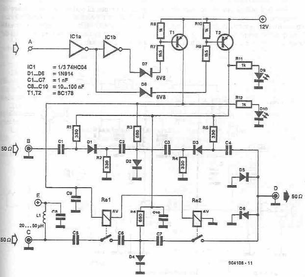
Antenna selector circuit diagram electronic project
This antenna selector circuit diagram electronic project is constructed using standard electronic components and facilitates the switching between two FM antennas through a logic signal. The gates IC1b and IC1a manage the switching and interface between the required logic levels...

Plug-in speed control for tools or appliances
Most standard household appliances and portable hand tools can be adapted for variable-speed operation using a simple half-wave SCR phase control. This device can serve as the speed control unit for typical loads, provided they utilize series universal (brush type)...

Simple SCR oscillator
Silicon controlled rectifiers (SCR) can easily oscillate if there is an inductor (a speaker coil in this case) which gives just enough extra voltage to completely switch off the sustain current. In this way a new cycle may start and...

Interfaces For The Remote-Control Transmitter Circuit
Several possible interface circuits are presented for use with a remote-control transmitter. The circuit labeled A demonstrates a typical FM stereo MUX decoder with a load connected directly to the open-collector output of a TA7343 PLL. The circuit labeled B...

SCR BRY35 For Simple Radio Control Circuit
The following circuit illustrates the SCR BRY35 used in a simple radio control circuit. Features include a straightforward and efficient receiver for operation.
The SCR BRY35 is a silicon-controlled rectifier designed to facilitate the control of high-power loads through low-power signals....

Closed-Loop Alarm Circuit
A string of three series-connected, normally closed switches is connected across the gate of a silicon-controlled rectifier (SCR). When one switch opens, the SCR is triggered through resistor R1, activating an alarm. The alarm is designed to be of the...