


Tunable IF with TDA7000
#TDA7000
#tunable IF
#receiver
#frequency indicator
#FET buffer
#oscillator coil
#RF circuit
#modification
#vintage electronics

Description: This circuit has suffered a lot of modifications over its long life. Even the lettering on the integrated circuit was partially erased over the years. The main motive of the mods was not that the circuit didn’t work right, but were several tries to add some kind of frequency indicator to the receiver. The left RCA plug and associated components are witnesses to the last version, adding a FET buffer amplifier and taking signal from the oscillator coil. None of the indicator systems was satisfactory, and the actual stability of the receiver oscillator was so good that it wasn’t really necessary either. A simple system with a preset resistor for each of the desired satellites was more than enough.
This circuit represents a modified receiver design that has undergone various iterations to enhance its functionality, particularly by integrating a frequency indicator system. The original circuit, while operational, prompted a series of modifications aimed at improving user feedback regarding frequency reception. The choice to utilize a FET (Field-Effect Transistor) buffer amplifier indicates a focus on maintaining signal integrity while interfacing with the oscillator coil.
The FET buffer amplifier serves to isolate the oscillator from the load, ensuring that the signal remains stable and free from distortion. This is particularly important in RF (radio frequency) applications where signal fidelity is crucial. The signal taken from the oscillator coil is indicative of the frequency being received, which can be crucial for tuning the receiver to specific satellites or frequencies.
The left RCA plug mentioned in the description likely serves as an output for the modified frequency indicator, allowing for external monitoring or interfacing with other devices. The modifications, while numerous, reflect an iterative design process where each version aimed to improve the circuit's performance. However, the final conclusion drawn from the modifications indicates that the inherent stability of the oscillator was sufficient for operation without the need for complex indicator systems.
The mention of a simple system with preset resistors for each desired satellite suggests a pragmatic approach to tuning, where each preset corresponds to a specific frequency. This method simplifies the user experience by allowing quick access to frequently used frequencies without the need for extensive adjustments.
Overall, the circuit exemplifies the balance between complexity and functionality in electronic design, demonstrating how iterative modifications can lead to a more user-friendly and effective device while maintaining the core operational integrity of the original design.This circuit has `suffered` a lot of modifications over its long life... Even the lettering on the integrated circuit was partially erased of the years. The main motive of the mods was not that the circuit didn`t work right, but were several tries to add some kind of frequency indicator to the receiver. The left RCA plug and associated components are witnesses to the last version, adding a FET buffer amplifiera and taking signal from the oscillator coil.
None of the indicator systems was satisfactory, and the actual stability of the receiver oscillator was so good that it wasn`t really necessary either. A simple system with a preset resistor for each of the the desired satellites was more than enough
This circuit represents a modified receiver design that has undergone various iterations to enhance its functionality, particularly by integrating a frequency indicator system. The original circuit, while operational, prompted a series of modifications aimed at improving user feedback regarding frequency reception. The choice to utilize a FET (Field-Effect Transistor) buffer amplifier indicates a focus on maintaining signal integrity while interfacing with the oscillator coil.
The FET buffer amplifier serves to isolate the oscillator from the load, ensuring that the signal remains stable and free from distortion. This is particularly important in RF (radio frequency) applications where signal fidelity is crucial. The signal taken from the oscillator coil is indicative of the frequency being received, which can be crucial for tuning the receiver to specific satellites or frequencies.
The left RCA plug mentioned in the description likely serves as an output for the modified frequency indicator, allowing for external monitoring or interfacing with other devices. The modifications, while numerous, reflect an iterative design process where each version aimed to improve the circuit's performance. However, the final conclusion drawn from the modifications indicates that the inherent stability of the oscillator was sufficient for operation without the need for complex indicator systems.
The mention of a simple system with preset resistors for each desired satellite suggests a pragmatic approach to tuning, where each preset corresponds to a specific frequency. This method simplifies the user experience by allowing quick access to frequently used frequencies without the need for extensive adjustments.
Overall, the circuit exemplifies the balance between complexity and functionality in electronic design, demonstrating how iterative modifications can lead to a more user-friendly and effective device while maintaining the core operational integrity of the original design.This circuit has `suffered` a lot of modifications over its long life... Even the lettering on the integrated circuit was partially erased of the years. The main motive of the mods was not that the circuit didn`t work right, but were several tries to add some kind of frequency indicator to the receiver. The left RCA plug and associated components are witnesses to the last version, adding a FET buffer amplifiera and taking signal from the oscillator coil.
None of the indicator systems was satisfactory, and the actual stability of the receiver oscillator was so good that it wasn`t really necessary either. A simple system with a preset resistor for each of the the desired satellites was more than enough

SW Receiver Using MK414
The tuned circuit consists of a variable capacitor and fixed air spaced coil. For the coil, wound between 10 and 20 turns of wire on an empty tube of around 1.5 inches diameter. The turns were spaced so that the...
Onkyo TX2500 mk II
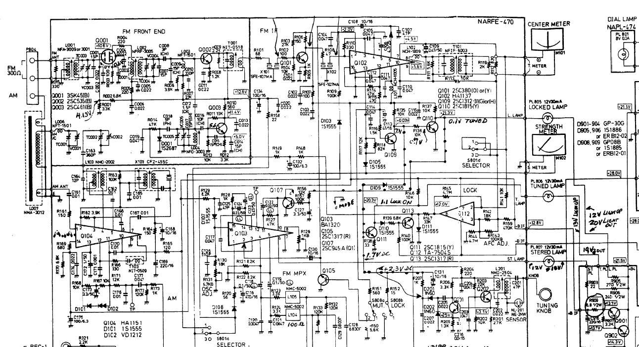
An Onkyo TX2500 mk II receiver is being repaired for a friend, but it is experiencing issues with both AM and FM tuning, resulting in low reception quality.
The Onkyo TX2500 mk II is a vintage audio receiver known for its...

REGENERATIVE_SHORTWAVE_RECEIVER
The receiver consists of multiple subassemblies, including an active antenna, an amplifier featuring regeneration control and band-switching circuitry, an AM detector, a power amplifier, and an output device such as an internal speaker, external speaker, or headphones. Additionally, it is...

41-72MHz micro-receiver ( MC3362 )
This receiver weighs about 6 g, used in 41 and 72 MHz, met a great success with readers of the magazine. The RX22 is the subject of these lines is improved RX20. Adding a preamp-HF improving sensitivity. Establishment of an...

A simple tuned radio frequency receiver
This simple tuned radio frequency receiver was designed and constructed in the mid-1990s. The receiver was tested under urban and field conditions, in varying temperatures. This straightforward circuit exhibits high sensitivity, good sound quality, and reliability. A signal received by...

5474 tips
The Aristo ART-5474 Accessory Panel is a complete receiver designed to control accessories using buttons A through E on the Train Engineer transmitter. The ART-5474 is capable of controlling two turnouts, one constant load such as lights, and can trigger...

Receiver monitor
The alarm connects to the earphone jack on a receiver. When a signal, typically sent to the headphones, is detected and applied to the gate of SCR1, it conducts, activating the alarm connected to SOI. The signaling device can be...

G3XTZ DF Rx Details
The receiver is constructed on a single-sided printed circuit board measuring 2 by 4.3 inches. Its compact size allows for installation in various enclosures, which should be adequately shielded. The main directional signal is captured by a tuned ferrite rod...

G0MRF 29.45 MHz Receiver Project
In 2007 and 2008, AMSAT-UK dedicated significant effort to a proposal for the European Space Agency (ESA) to include an Amateur Radio payload on the mass dummy during the maiden flight of the VEGA launcher. This initiative was referred to...