


Video modulator circuit
#video modulator
#VHF
#UHF
#modulation
#carrier signal
#5V power supply
#negative modulation
#positive modulation
#clamp circuit

Description: These are modulator circuits designed for the modulation of video signals on a VHF/UHF carrier. The circuits require a 5 V power supply and a few external components for negative modulation mode. For positive modulation, an external clamp circuit is necessary. The circuits can function as general-purpose modulators without the need for additional external components. The integrated circuit (IC) used is the TDA6800.
The TDA6800 is a versatile integrated circuit specifically designed for modulating video signals onto VHF and UHF carriers. This modulator circuit is suitable for applications in television broadcasting, video transmission, and other related fields.
The circuit operates at a nominal power supply of 5 V, which is essential for the proper functioning of the IC and the modulation process. In negative modulation mode, the circuit requires a minimal number of external components, which typically include resistors and capacitors for filtering and stabilization. This simplicity allows for easy integration into various systems.
For positive modulation, an external clamp circuit is required to ensure that the video signal is properly biased for modulation. This clamp circuit can be implemented using a diode and a capacitor, which helps to maintain the signal level within the desired range and avoid distortion during the modulation process.
The TDA6800 IC itself contains all necessary circuitry for generating the modulation signal and can provide high-quality output with minimal distortion. Its design allows for flexibility in modulation schemes, making it suitable for a wide range of video applications. Additionally, the IC supports general-purpose modulation without the need for extensive additional components, enhancing its utility in various electronic designs.
Overall, the TDA6800 modulator circuits are efficient and effective solutions for video signal modulation, providing a reliable method for transmitting video over VHF and UHF frequencies.These are modulator circuits for modulation of video signals on a VHF/UHF carrier. The circuits require a 5 V power supply and few external components for the negative modulation mode. For positive modulation an external clamp circuit is required. The circuits can be used as general-purpose modulators without additional external components. The IC is TDA6800.
The TDA6800 is a versatile integrated circuit specifically designed for modulating video signals onto VHF and UHF carriers. This modulator circuit is suitable for applications in television broadcasting, video transmission, and other related fields.
The circuit operates at a nominal power supply of 5 V, which is essential for the proper functioning of the IC and the modulation process. In negative modulation mode, the circuit requires a minimal number of external components, which typically include resistors and capacitors for filtering and stabilization. This simplicity allows for easy integration into various systems.
For positive modulation, an external clamp circuit is required to ensure that the video signal is properly biased for modulation. This clamp circuit can be implemented using a diode and a capacitor, which helps to maintain the signal level within the desired range and avoid distortion during the modulation process.
The TDA6800 IC itself contains all necessary circuitry for generating the modulation signal and can provide high-quality output with minimal distortion. Its design allows for flexibility in modulation schemes, making it suitable for a wide range of video applications. Additionally, the IC supports general-purpose modulation without the need for extensive additional components, enhancing its utility in various electronic designs.
Overall, the TDA6800 modulator circuits are efficient and effective solutions for video signal modulation, providing a reliable method for transmitting video over VHF and UHF frequencies.These are modulator circuits for modulation of video signals on a VHF/UHF carrier. The circuits require a 5 V power supply and few external components for the negative modulation mode. For positive modulation an external clamp circuit is required. The circuits can be used as general-purpose modulators without additional external components. The IC is TDA6800.
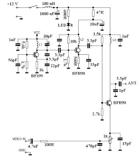
Simple UHF Video Transmitter
This video transmitter circuit operates on the UHF channel frequency of 470-580 MHz, specifically channels 21-34. It can transmit video signals over distances ranging from 30 to 100 meters when using a cable length of 10 to 20 cm. For...

High-Pass Filter controls UHF Ingress to Satellite DBS Tuner
This application note discusses the design of a UHF ingress filter intended for a Satellite DBS tuner. The filter is designed to achieve 20 dB of stopband attenuation within the frequency range of 54-650 MHz, while maintaining an in-band insertion...

20dB VHF AmplifierCircuit Using BF197 Transistor
The following circuit illustrates a 20 dB VHF amplifier circuit diagram utilizing the BF197 transistor. Features include a simple circuit design.
The 20 dB VHF amplifier circuit is designed to amplify very high frequency signals, making it suitable for applications such...

VHF 5/8wave vertical antennas
At VHF, both the 1/4-wavelength monopole and the 5/8-wavelength monopole antennas are widely used. The VHF 5/8-wavelength (144 MHz) vertical monopole has long held the reputation of providing about a 3-dB gain advantage over the 1/4-wavelength vertical monopole. The foundation...

15dB UHF TV Antenna Amplifier
This is a UHF band TV antenna preamplifier circuit with 15dB gain to build easily. It is formed based on BF180 UHF Transistor. The first stage is a band pass filter constructed by the C1, CV1, L1, L4, C7, and...

Simple UHF oscillator
This oscillator is typical for operation between 350 to 500 MHz. The microstrip inductor is implemented as a printed circuit board (PCB) trace. The output power ranges from 55 to 100 mW into a 50-ohm load, with frequency stability typically...
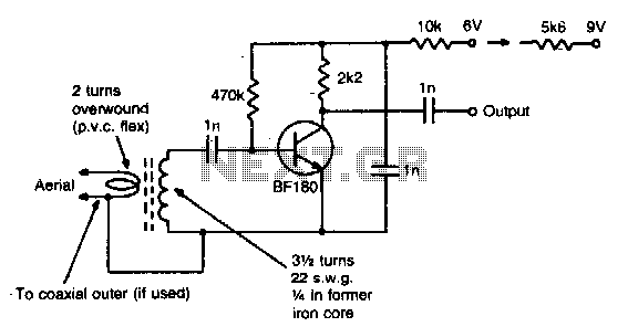
Vhf preamplifier
This simple circuit provides a gain of 15 dB and can be mounted on a 1 inch by 2 inch PCB. Coil specifications are provided for a frequency range of 85 to 95 MHz. For other frequencies, the coil should...

15db uhf tv antenna booster
This is a UHF band TV antenna preamplifier circuit with a gain of 15 dB. It is designed using the BF180 UHF transistor. The input stage consists of a band-pass filter implemented with components C1, CV1, L1, L4, C7, and...

VHF preamplifier with BFY91
When the start switch is pushed, the output of the charger goes to 14.5 V. As the battery approaches full charge, the charging current decreases and the output voltage is reduced from 14.5V to about 12.5V, terminating the charging process....