


74HC11 Infra-Red Remote Control Tester
#infra-red
#IR tester
#remote control
#3V battery
#compact design
#inexpensive parts
#analogue amplifier
#go/no-go test

Description: This circuit is an Infra-Red Remote Control Tester designed to verify the functionality of any remote control that transmits infrared (IR) light. It operates on a 3V battery and offers several advantages, such as its compact size and the use of inexpensive, commonly available components. The circuit employs a Schmitt trigger gate (IC1f) in conjunction with an infrared emitting diode (IRED) of type LD274. Since all IR remote controls transmit pulse bursts, an R-C network consisting of capacitor C1 and resistor R2 is implemented at the output of the gate. Additionally, another R-C network is utilized to prevent the output LED (D2) from illuminating continuously when exposed to external IR light sources or daylight.
This Infra-Red Remote Control Tester circuit is a straightforward yet effective tool for determining the operational status of remote controls. The circuit's core component, the Schmitt trigger gate, provides a stable output by converting the varying input signals from the IRED into a clean digital signal. The IRED emits infrared light when activated, which is detected by the remote control. The pulse bursts from the remote are captured by the circuit, which then processes these signals.
The R-C network at the output serves a dual purpose. Firstly, it smooths out the pulse signals, ensuring that the output remains stable while the remote is in operation. Secondly, the additional R-C network prevents false triggering of the output LED, which could occur due to ambient IR light sources. This feature is particularly useful in environments with significant background IR interference, such as those illuminated by sunlight or other IR-emitting devices.
In terms of construction, the circuit can be assembled on a small printed circuit board (PCB) or a breadboard, allowing for easy prototyping and testing. The choice of components is critical; therefore, it is recommended to use a high-quality IRED and a reliable Schmitt trigger IC to ensure consistent performance. The LED indicator (D2) provides a visual confirmation of the remote's operation, lighting up only when the correct IR signals are detected.
Overall, this Infra-Red Remote Control Tester circuit exemplifies an efficient design that balances simplicity, cost-effectiveness, and functionality, making it an excellent tool for both hobbyists and professionals in the field of electronics.This is Infra-Red Remote Control Tester circuit. This circuit is used to test go/no-go of any remote control transmitting infra-red (IR) light. The supply of this circuit is 3V battery. This circuit has some advantages, such as fits in a compact enclosure, built from inexpensive parts and a handful of commonly available. As a quasi-analogue amplif ier, this circuit uses Schmitt trigger gate IC1f with the sensor element. The sensor element is an infra-red emitting diode (IRED) type LD274. All IR remote controls transmit pulse bursts, so an R-C network, C1-R2, is used at the output of the gate. Beside that, An R-C network is also used to prevent the output LED, D2, lighting constantly when another continuous source of IR light or day-light is detected.
[Circuit`s schematic diagram source: extremecircuits. net] We aim to transmit more information by carrying articles. Please send us an E-mail to wanghuali@hqew. net within 15 days if we are involved in the problems of article content, copyright or other problems. We will delete it soon.
This Infra-Red Remote Control Tester circuit is a straightforward yet effective tool for determining the operational status of remote controls. The circuit's core component, the Schmitt trigger gate, provides a stable output by converting the varying input signals from the IRED into a clean digital signal. The IRED emits infrared light when activated, which is detected by the remote control. The pulse bursts from the remote are captured by the circuit, which then processes these signals.
The R-C network at the output serves a dual purpose. Firstly, it smooths out the pulse signals, ensuring that the output remains stable while the remote is in operation. Secondly, the additional R-C network prevents false triggering of the output LED, which could occur due to ambient IR light sources. This feature is particularly useful in environments with significant background IR interference, such as those illuminated by sunlight or other IR-emitting devices.
In terms of construction, the circuit can be assembled on a small printed circuit board (PCB) or a breadboard, allowing for easy prototyping and testing. The choice of components is critical; therefore, it is recommended to use a high-quality IRED and a reliable Schmitt trigger IC to ensure consistent performance. The LED indicator (D2) provides a visual confirmation of the remote's operation, lighting up only when the correct IR signals are detected.
Overall, this Infra-Red Remote Control Tester circuit exemplifies an efficient design that balances simplicity, cost-effectiveness, and functionality, making it an excellent tool for both hobbyists and professionals in the field of electronics.This is Infra-Red Remote Control Tester circuit. This circuit is used to test go/no-go of any remote control transmitting infra-red (IR) light. The supply of this circuit is 3V battery. This circuit has some advantages, such as fits in a compact enclosure, built from inexpensive parts and a handful of commonly available. As a quasi-analogue amplif ier, this circuit uses Schmitt trigger gate IC1f with the sensor element. The sensor element is an infra-red emitting diode (IRED) type LD274. All IR remote controls transmit pulse bursts, so an R-C network, C1-R2, is used at the output of the gate. Beside that, An R-C network is also used to prevent the output LED, D2, lighting constantly when another continuous source of IR light or day-light is detected.
[Circuit`s schematic diagram source: extremecircuits. net] We aim to transmit more information by carrying articles. Please send us an E-mail to wanghuali@hqew. net within 15 days if we are involved in the problems of article content, copyright or other problems. We will delete it soon.
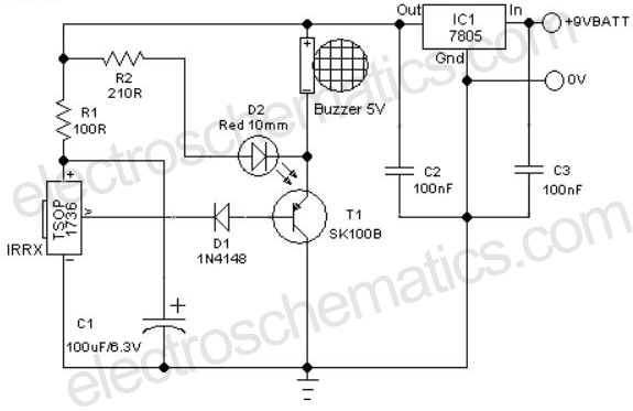
Remote Controlled Alarm circuit
A remote-controlled alarm circuit utilizing the TSOP1736 is designed for easy use by elderly individuals or patients confined to bed. This battery-operated alarm system eliminates the need for routing electric cables to a calling bell switch, making it a practical...

Remote Control Mains Switch
The request for assistance came from an elderly lady in a retirement home. In her room, the light switch by the door and the pull cord above the bed control the ceiling light fitting. However, she prefers to operate her...

The eight-way remote control circuit diagram composed of module
This is an eight-way signal remote control selection circuit composed of ZHJ-9904. It includes a remote control transmitter circuit, an eight-way switch control circuit, and a remote control transmitter.
The eight-way signal remote control selection circuit utilizing the ZHJ-9904 is designed...
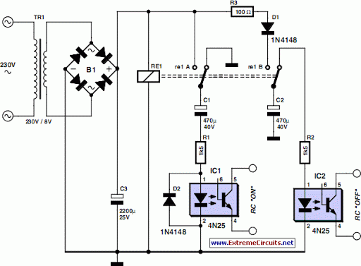
remote control mains switch
As the only electronics engineer in the family and circle of friends, it is sometimes challenging to decline requests for assistance. Recently, a friendly elderly lady in a retirement home sought help regarding her lighting situation. In her room, the...

remote shift light
Replacing the resistor/transistor with an n-channel power MOSFET and substituting the relay/protection diode with a light bulb results in a simplified circuit that mirrors the original design, provided one end of the light bulb is connected to +12V. If the...
The eight-way remote control circuit diagram composed of module
This is an eight-way signal remote control selection circuit composed of ZHJ-9904. It includes a remote control transmitter circuit, an eight-way switch control circuit, and a remote control transmitter.
The eight-way signal remote control selection circuit utilizing the ZHJ-9904 is designed...

Remote Controlled Fan Regulator EEE Project Report
This report presents a comprehensive overview of a mini project titled "Remote Controlled Fan Regulator," developed in accordance with the curriculum requirements for the sixth semester of the Bachelor of Technology degree in Electrical and Electronics Engineering. The report is...

Remote control robot circuit
The remote control robot circuit is illustrated in the accompanying figure. Figure 2-36(a) presents the circuit diagram, while figure 2-36(b) depicts the operating timing diagram. The robot's rotation process involves an ultrasonic launching circuit, which consists of a 40 kHz...

Remote schematic CSJ-T300B with CSJ-R02B composition
The CSJ-T300B/CSJ-R02B is an enhanced digital encoding and decoding circuit developed based on the CSJ-T300A/CSJ-R02A. It forms a remote control circuit that includes the CSJ-T300B and CSJ-R02B components, as illustrated below.
The CSJ-T300B/CSJ-R02B circuit architecture is designed to facilitate improved digital...