


aam commander rc system
#RC system
#remote control
#1972
#American Aircraft Modeler
#vintage electronics
#radio control
#model aircraft
#scanned article
#retro tech

Description: Part II of the AAM Commander RC System Article, scanned from the May 1972 edition of American Aircraft Modeler.
The AAM Commander RC System is a sophisticated radio control system designed for model aircraft, providing enhanced control and performance for hobbyists and enthusiasts. This system typically includes a transmitter, receiver, servos, and various electronic components that facilitate communication between the pilot and the model aircraft.
The transmitter serves as the control interface for the pilot, allowing for the manipulation of various control surfaces such as ailerons, elevators, and rudders. It operates on specific radio frequencies, ensuring reliable signal transmission to the receiver installed in the aircraft. The receiver, in turn, interprets the signals from the transmitter and translates them into mechanical movements through servos, which are responsible for adjusting the control surfaces accordingly.
In addition to the basic components, the AAM Commander RC System may incorporate features such as dual rates, which allow pilots to switch between different sensitivity settings for control inputs, and mixing capabilities that enable complex maneuvers by combining inputs from multiple channels. The system is designed to be user-friendly, ensuring that both novice and experienced pilots can operate their model aircraft with precision and ease.
The electronic schematic of the AAM Commander RC System would typically include the following key elements:
1. **Transmitter Circuit**: This section includes the oscillator circuit, modulation circuits, and power supply components that generate and transmit radio signals. The transmitter may utilize a microcontroller for signal processing and control logic.
2. **Receiver Circuit**: The receiver circuit includes an antenna, RF amplifier, demodulator, and servo output stage. The antenna captures the incoming radio signals, which are amplified and demodulated to extract the control information.
3. **Servo Control**: The servos are controlled by PWM (Pulse Width Modulation) signals generated by the receiver. The schematic would show the connection of the receiver output pins to the servo inputs, detailing the power supply and ground connections.
4. **Power Supply**: The power supply circuit is crucial for both the transmitter and receiver, ensuring that all components operate within their specified voltage and current ratings. It may include voltage regulators and filtering capacitors to stabilize the power supply.
5. **Antenna Design**: The schematic may also depict the design of the antenna used for both the transmitter and receiver, which is essential for achieving optimal range and minimizing interference.
Overall, the AAM Commander RC System represents a well-engineered solution for model aircraft control, showcasing the integration of various electronic components to enhance the flying experience.Part II of the AAM Commander RC System Article, scanned from the May 1972 edition of American Aircraft Modeler..
The AAM Commander RC System is a sophisticated radio control system designed for model aircraft, providing enhanced control and performance for hobbyists and enthusiasts. This system typically includes a transmitter, receiver, servos, and various electronic components that facilitate communication between the pilot and the model aircraft.
The transmitter serves as the control interface for the pilot, allowing for the manipulation of various control surfaces such as ailerons, elevators, and rudders. It operates on specific radio frequencies, ensuring reliable signal transmission to the receiver installed in the aircraft. The receiver, in turn, interprets the signals from the transmitter and translates them into mechanical movements through servos, which are responsible for adjusting the control surfaces accordingly.
In addition to the basic components, the AAM Commander RC System may incorporate features such as dual rates, which allow pilots to switch between different sensitivity settings for control inputs, and mixing capabilities that enable complex maneuvers by combining inputs from multiple channels. The system is designed to be user-friendly, ensuring that both novice and experienced pilots can operate their model aircraft with precision and ease.
The electronic schematic of the AAM Commander RC System would typically include the following key elements:
1. **Transmitter Circuit**: This section includes the oscillator circuit, modulation circuits, and power supply components that generate and transmit radio signals. The transmitter may utilize a microcontroller for signal processing and control logic.
2. **Receiver Circuit**: The receiver circuit includes an antenna, RF amplifier, demodulator, and servo output stage. The antenna captures the incoming radio signals, which are amplified and demodulated to extract the control information.
3. **Servo Control**: The servos are controlled by PWM (Pulse Width Modulation) signals generated by the receiver. The schematic would show the connection of the receiver output pins to the servo inputs, detailing the power supply and ground connections.
4. **Power Supply**: The power supply circuit is crucial for both the transmitter and receiver, ensuring that all components operate within their specified voltage and current ratings. It may include voltage regulators and filtering capacitors to stabilize the power supply.
5. **Antenna Design**: The schematic may also depict the design of the antenna used for both the transmitter and receiver, which is essential for achieving optimal range and minimizing interference.
Overall, the AAM Commander RC System represents a well-engineered solution for model aircraft control, showcasing the integration of various electronic components to enhance the flying experience.Part II of the AAM Commander RC System Article, scanned from the May 1972 edition of American Aircraft Modeler..

200 meters remote control schematic design
Early transmitters using LC oscillators experience significant frequency drift. The introduction of Surface Acoustic Wave (SAW) devices addresses this issue, providing substantial frequency stability comparable to crystals. These devices can achieve fundamental frequencies in the hundreds of megahertz or even...
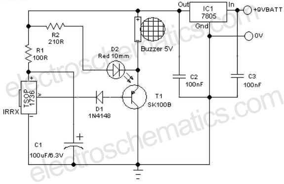
Remote Controlled Alarm circuit
A remote-controlled alarm circuit utilizing the TSOP1736 is designed for easy use by elderly individuals or patients confined to bed. This battery-operated alarm system eliminates the need for routing electric cables to a calling bell switch, making it a practical...

Modern Electronic Remote Controls
Modern ICON electronic engine controls from BRP
The ICON electronic engine control system developed by Bombardier Recreational Products (BRP) represents a significant advancement in marine technology. This system integrates sophisticated electronic controls to enhance the performance and reliability of marine engines....

Accident Prevention and Security System for Automobiles
This is a remote-controlled land rover that can be operated using a cell phone. This allows the user to move the land rover by sending various commands from their device. The rover can be controlled from virtually anywhere in the...
remote
Each unit features four channels, enabling the programming and operation of up to four separate devices with a single remote, provided these devices operate on the same frequency. The unit can automatically learn from existing garage door remotes or built-in...

Radio control
A simple and effective receiver for actuating garage doors, alarms, warning systems, etc. The SCR, which has a very low trigger current of 30 µA, requires an input power of only 30 µW to activate the relay. A high Q...

door opener science project
This button, with some modifications, allows the opening of an office door using Nexus One, iPhone, or SMS. Positioned near the reception desk, this button activates an electronic latch on the front door. Upon removing the assembly from the wall,...

multiple unit radio control
Multiple unit radio control: How to create a multi-unit radio control system.
A multi-unit radio control system allows for the simultaneous operation of multiple devices or units using a single remote control transmitter. This system is commonly used in various applications,...

Core Remote Control Unit
If the unit has been idle for an extended period due to depleted AAA batteries, resulting in a malfunctioning display or inoperability, the most likely requirement is the replacement of the internal lithium battery. Although the unit was advanced for...