


Carrier current remote control device or intercom circuit diagram
#carrier current
#remote control
#intercom
#communication
#wireless
#audio
#transmitter
#receiver
#home automation
#telecommunication

Description: Carrier current remote control device or intercom circuit diagram as follows:
The circuit diagram for a carrier current remote control device or intercom system typically involves the use of carrier current technology to transmit audio signals over existing electrical wiring. This system allows for communication between different points without the need for dedicated wiring, utilizing the electrical infrastructure already in place.
The primary components of this circuit include a microphone, an audio amplifier, a modulator, and a demodulator. The microphone captures the audio input, which is then amplified by the audio amplifier to ensure sufficient signal strength. The modulator converts the audio signal into a high-frequency carrier wave suitable for transmission over the electrical lines.
The carrier wave is then sent through the power lines, where it can travel to various locations within the building. At the receiving end, the demodulator extracts the audio signal from the carrier wave, allowing it to be played back through a speaker or another audio output device.
Additional components may include filters to reduce noise and improve signal clarity, as well as power supply circuits to ensure the system operates efficiently. The design must also consider impedance matching to optimize the transmission of audio signals and minimize signal loss.
This type of intercom system is particularly advantageous in residential or commercial settings where installing new wiring is impractical. By leveraging existing electrical infrastructure, carrier current intercom systems provide a cost-effective and efficient solution for communication needs. Carrier current remote control device or intercom circuit diagram as follows:
The circuit diagram for a carrier current remote control device or intercom system typically involves the use of carrier current technology to transmit audio signals over existing electrical wiring. This system allows for communication between different points without the need for dedicated wiring, utilizing the electrical infrastructure already in place.
The primary components of this circuit include a microphone, an audio amplifier, a modulator, and a demodulator. The microphone captures the audio input, which is then amplified by the audio amplifier to ensure sufficient signal strength. The modulator converts the audio signal into a high-frequency carrier wave suitable for transmission over the electrical lines.
The carrier wave is then sent through the power lines, where it can travel to various locations within the building. At the receiving end, the demodulator extracts the audio signal from the carrier wave, allowing it to be played back through a speaker or another audio output device.
Additional components may include filters to reduce noise and improve signal clarity, as well as power supply circuits to ensure the system operates efficiently. The design must also consider impedance matching to optimize the transmission of audio signals and minimize signal loss.
This type of intercom system is particularly advantageous in residential or commercial settings where installing new wiring is impractical. By leveraging existing electrical infrastructure, carrier current intercom systems provide a cost-effective and efficient solution for communication needs. Carrier current remote control device or intercom circuit diagram as follows:

1.5 Volt Tracking Transmitter
A 1.5 Volt tracking transmitter utilizing simple circuits. The current draw for this tracker is 3.7 mA, allowing the 1.5V button cell to have a prolonged lifespan.
The 1.5 Volt tracking transmitter is designed to operate efficiently with a low current...

Audio Tone control in Line amplifier
This rule allows the amp volume, balance and tone controls to take. The circuit operates a specially designed IC, LM 1036. The advantage is that few external components and to control monopotmeters can be used, which are cheaper. The schedule...

valved transmitter for 3.5 MHz
This transmitter project is a highly efficient, rugged, and simple low-power continuous wave (C.W.) unit delivering more than 10W. It is crystal-controlled with stabilized high tension (H.T.) and features a buffer stage between the crystal oscillator and power amplifier stages,...

Dummy Transmission Circuits for Subcutaneous Transmitter
The project involves the development of a miniature transmitter suitable for implantation in a rat's body, capable of transmitting 416-bit data samples at a rate of 400 samples per second. It is designed to have a detection range of three...

Circuit Audio Stereo power amplifier LM4755 11W with Mute
The internal mute circuit and pre-set gain resistors provide a cost-effective design solution. Output power specifications at both 20V and 24V supplies, along with a low external component count, offer significant value to consumer electronic manufacturers for stereo TV and...
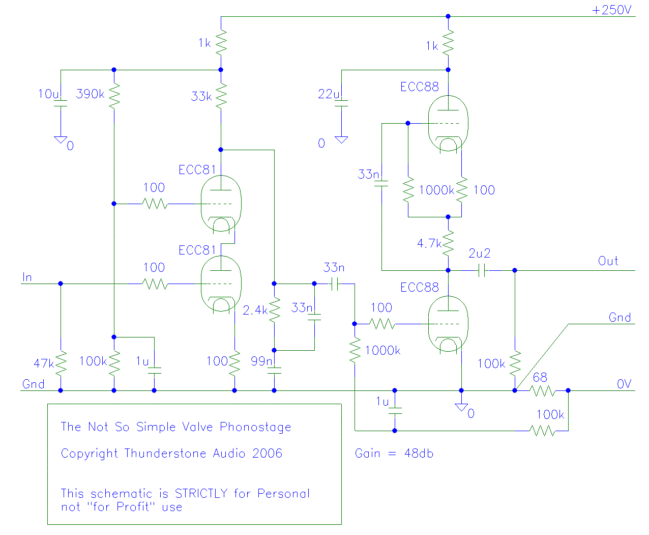
New Phono amp
Very interesting points Chris and Thorsten, but I would like to take a moment to revisit my latest design, which is represented in the attached schematic.
The attached schematic represents a recent design that integrates various electronic components to achieve a...
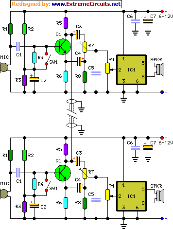
Full-duplex Intercom
This design enables the operation of two intercom stations, allowing the operator to remain hands-free for other tasks, thus eliminating the typical push-to-talk operation mode. No complex changeover switching is necessary; the two units are interconnected using a thin screened...

wireless telephone line spy circuit
This design outlines a phone bug circuit. The wireless telephone line spy circuit is capable of transmitting phone conversations to a nearby FM radio. The circuit must be connected to a standard phone line. In the circuit, the first transistor...
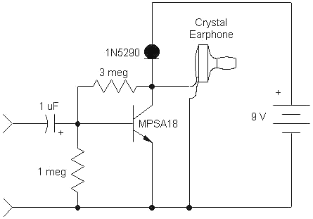
Audio High Gain Crystal Earphone Amplifier
This simple, one-transistor amplifier provides a voltage gain of over 1000 (60 dB) for an active aerial impedance crystal earphone. The gain is achieved by replacing the standard load resistor with a constant-current diode that supplies 1/2 mA while exhibiting...