


IR Remote Control Extender circuit diagrams
#IR remote
#noise immunity
#extender circuit
#36-38kHz
#remote control range
#ambient light resistance
#reflected light resistance
#domestic apparatus
#IR carrier frequency

Description: This is an enhanced infrared (IR) remote control extender circuit that exhibits high noise immunity, resistance to ambient and reflected light, and an extended operational range of approximately 7 meters between the remote control and the extender circuit. It is designed to be compatible with any domestic devices that utilize a 36-38 kHz IR carrier frequency. However, it is important to note that this circuit is not compatible with certain satellite receivers that operate at a carrier frequency of 115 kHz. The primary distinction between this version and the previous iteration is the incorporation of a commercially available infrared module, designated as IR1, which can be sourced from Harrison Electronics in the UK. This module integrates a built-in photodiode, amplifier circuit, buffer, and decoder, centered around the common 38 kHz carrier frequency utilized by most IR controls. The module effectively removes the majority of the carrier signal, allowing only the decoded pulses to be transmitted to the appliance. Domestic televisions and VCRs employ additional filtering to entirely eliminate the carrier.
The IR1 module (IC3) operates on a 5-volt DC supply, which is provided by the 7805 voltage regulator (IC1). Under quiescent conditions, without any IR signal, the output pin maintains a high voltage of approximately 5 volts DC. This output needs to be inverted and buffered for driving the IR phototransmitter LED (LED2). The buffering is achieved using one gate (pins 2 & 3) of a hex inverter, the CMOS 4049 (IC2). Although the IR1 module can directly drive TTL logic, a pull-up resistor (R4) is necessary for interfacing with CMOS ICs. This resistor guarantees that the signal from the remote control oscillates between 0 and 5 volts. Given that TTL logic levels differ slightly from CMOS, the 3.3k resistor (R4) is connected to the +5 volt supply line, ensuring that the logic high signal remains at 5 volts rather than the TTL level of 3.3 volts. While this resistor does not impact the performance of the IR module, it ensures stable operation when driving the CMOS buffer.
The output from pin 2 of the 4049 directly drives transistor Q1, with a 10k resistor (R1) limiting the base current. LED1, a red LED, flickers to indicate the reception of a signal from a remote control. It is noteworthy that in this circuit, the carrier signal is still present, albeit at a reduced level, alongside the decoded IR signal. The CMOS 4049 and BC109C transistor amplify both the carrier and the signal, driving LED2 at a peak current of approximately 120 mA when a signal is detected. Measurement with a digital multimeter may yield a lower reading, typically around 30 mA, as the meter captures the average DC value rather than the peak current. Devices designed to operate within the 36 to 40 kHz range should function effectively with this circuit, although controls operating at frequencies outside this range may experience reduced operational range. An exception to this compatibility is noted with some satellite receivers that utilize IR controls modulated at approximately 115 kHz, which are currently not supported by this circuit. Future iterations, such as a Mark 3 version, are being developed to address this limitation by reintroducing the carrier signal.This is an improved IR remote control extender circuit. It has high noise immunity, is resistant to ambient and reflected light and has an increased range from remote control to the extender circuit of about 7 meters. It should work with any domestic apparatus that use 36-38kHz for the IR carrier frequency. Please note that this is NOT compatible with some satellite receivers that use 115KHz as a carrier frequency. The main difference between this version and the previous circuit, is that this design uses a commercially available Infra Red module. This module, part number IR1 is available from Harrison Electronics in the UK. The IR module contains a built in photo diode, amplifier circuit and buffer and decoder. It is centerd on the common 38kHz carrier frequency that most IR controls use. The module removes most of the carrier allowing decoded pulses to pass to the appliance. Domestic TV`s and VCR`s use extra filtering is used to completely remove the carrier. The IR1 is packaged in a small aluminium case, the connections viewed from underneath are shown below: The IR1 module (IC3) operates on 5 Volt dc.
This is provided by the 7805 voltage regulator, IC1. Under quiescent (no IR signal) conditions the voltage on the output pin is high, around 5 volts dc. This needs to be inverted and buffered to drive the IR photo emitter LED, LED2. The buffering is provided by one gate (pins 2 & 3) of a hex invertor the CMOS 4049, IC2. The IR1 module can directly drive TTL logic, but a pull-up resistor, R4 is required to interface to CMOS IC`s. This resistor ensures that the signal from a remote control will alternate between 0 and 5 volts. As TTL logic levels are slightly different from CMOS, the 3. 3k resistor R4 is wired to the +5 volt supply line ensuring that the logic high signal will be 5 volts and not the TTL levels 3.
3 volts. The resistor does not affect performance of the IR module, but DOES ensure that the module will correctly drive the CMOS buffer without instability. The output from the 4049 pin 2 directly drives transistor Q1, the 10k resistor R1 limiting base current.
LED1 is a RED LED, it will flicker to indicate when a signal from a remote control is received. Note that in this circuit, the carrier is still present, but at a reduced level, as well as the decoded IR signal. The CMOS 4049 and BC109C transistor will amplify both carrier and signal driving LED2 at a peak current of about 120 mA when a signal is received.
If you try to measure this with a digital meter, it will read much less, probably around 30mA as the meter will measure the average DC value, not the peak current. Any equipment designed to work between 36 and 40kHz should work, any controls with carrier frequencies outside this limit will have reduced range, but should work.
The exception here is that some satellite receivers have IR controls that use a higher modulated carrier of around 115KHz. At present, these DO NOT work with my circuit, however I am working on a Mark 3 version to re-introduce the carrier.
The IR1 module (IC3) operates on a 5-volt DC supply, which is provided by the 7805 voltage regulator (IC1). Under quiescent conditions, without any IR signal, the output pin maintains a high voltage of approximately 5 volts DC. This output needs to be inverted and buffered for driving the IR phototransmitter LED (LED2). The buffering is achieved using one gate (pins 2 & 3) of a hex inverter, the CMOS 4049 (IC2). Although the IR1 module can directly drive TTL logic, a pull-up resistor (R4) is necessary for interfacing with CMOS ICs. This resistor guarantees that the signal from the remote control oscillates between 0 and 5 volts. Given that TTL logic levels differ slightly from CMOS, the 3.3k resistor (R4) is connected to the +5 volt supply line, ensuring that the logic high signal remains at 5 volts rather than the TTL level of 3.3 volts. While this resistor does not impact the performance of the IR module, it ensures stable operation when driving the CMOS buffer.
The output from pin 2 of the 4049 directly drives transistor Q1, with a 10k resistor (R1) limiting the base current. LED1, a red LED, flickers to indicate the reception of a signal from a remote control. It is noteworthy that in this circuit, the carrier signal is still present, albeit at a reduced level, alongside the decoded IR signal. The CMOS 4049 and BC109C transistor amplify both the carrier and the signal, driving LED2 at a peak current of approximately 120 mA when a signal is detected. Measurement with a digital multimeter may yield a lower reading, typically around 30 mA, as the meter captures the average DC value rather than the peak current. Devices designed to operate within the 36 to 40 kHz range should function effectively with this circuit, although controls operating at frequencies outside this range may experience reduced operational range. An exception to this compatibility is noted with some satellite receivers that utilize IR controls modulated at approximately 115 kHz, which are currently not supported by this circuit. Future iterations, such as a Mark 3 version, are being developed to address this limitation by reintroducing the carrier signal.This is an improved IR remote control extender circuit. It has high noise immunity, is resistant to ambient and reflected light and has an increased range from remote control to the extender circuit of about 7 meters. It should work with any domestic apparatus that use 36-38kHz for the IR carrier frequency. Please note that this is NOT compatible with some satellite receivers that use 115KHz as a carrier frequency. The main difference between this version and the previous circuit, is that this design uses a commercially available Infra Red module. This module, part number IR1 is available from Harrison Electronics in the UK. The IR module contains a built in photo diode, amplifier circuit and buffer and decoder. It is centerd on the common 38kHz carrier frequency that most IR controls use. The module removes most of the carrier allowing decoded pulses to pass to the appliance. Domestic TV`s and VCR`s use extra filtering is used to completely remove the carrier. The IR1 is packaged in a small aluminium case, the connections viewed from underneath are shown below: The IR1 module (IC3) operates on 5 Volt dc.
This is provided by the 7805 voltage regulator, IC1. Under quiescent (no IR signal) conditions the voltage on the output pin is high, around 5 volts dc. This needs to be inverted and buffered to drive the IR photo emitter LED, LED2. The buffering is provided by one gate (pins 2 & 3) of a hex invertor the CMOS 4049, IC2. The IR1 module can directly drive TTL logic, but a pull-up resistor, R4 is required to interface to CMOS IC`s. This resistor ensures that the signal from a remote control will alternate between 0 and 5 volts. As TTL logic levels are slightly different from CMOS, the 3. 3k resistor R4 is wired to the +5 volt supply line ensuring that the logic high signal will be 5 volts and not the TTL levels 3.
3 volts. The resistor does not affect performance of the IR module, but DOES ensure that the module will correctly drive the CMOS buffer without instability. The output from the 4049 pin 2 directly drives transistor Q1, the 10k resistor R1 limiting base current.
LED1 is a RED LED, it will flicker to indicate when a signal from a remote control is received. Note that in this circuit, the carrier is still present, but at a reduced level, as well as the decoded IR signal. The CMOS 4049 and BC109C transistor will amplify both carrier and signal driving LED2 at a peak current of about 120 mA when a signal is received.
If you try to measure this with a digital meter, it will read much less, probably around 30mA as the meter will measure the average DC value, not the peak current. Any equipment designed to work between 36 and 40kHz should work, any controls with carrier frequencies outside this limit will have reduced range, but should work.
The exception here is that some satellite receivers have IR controls that use a higher modulated carrier of around 115KHz. At present, these DO NOT work with my circuit, however I am working on a Mark 3 version to re-introduce the carrier.

ir remote circuit
This is a simple schematic designed to control a lamp using a Sony TV remote control. The circuit employs a PWM signal connected to a photocoupler, which isolates the power section from the microcontroller. The power section features an innovative...

Hampton Bay Air Conditioner IR Remote Control Reverse Engineer
Electronics Nerd demonstrates the process of reverse engineering an infrared (IR) remote control signal. By understanding the type of signal transmitted by the remote, a microcontroller can be programmed to simulate the code necessary to control the Hampton Bay Air...

Circuit for controlling 8 appliances using TV Remote
The infrared (IR) circuit is designed to control multiple devices using a TV remote. Unlike standard circuits that can typically switch only one device, this circuit allows for the operation of different devices with the same remote by utilizing distinct...

Nikon IR-Remote Control
An infrared (IR) remote control designed for a Nikon DSLR camera. While not essential, it serves as an interesting project. The protocol used by the original Nikon remote controls ML-L1 and ML-L3 is straightforward, as explained by Big Mike on...

IR remote control relays
4 Channel Infrared (IR) Remote is a simple kit using the famous HT12A and HT12D encoder/decoder chips from Holtek.
The 4 Channel Infrared (IR) Remote system utilizes the HT12A and HT12D integrated circuits to facilitate wireless communication between a transmitter and...
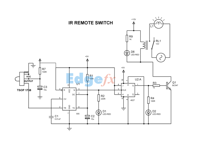
IR Remote Control Switch
This document explains a simple circuit designed to remotely switch on or off any electrical device using a relay, controlled by a standard TV or VCR.
The circuit utilizes a relay as the primary switching element, enabling the control of high-power...

IR remote control for PC
This simple circuit allows you to record any IR remote control signal on your PC, and then play it back. This is particularly useful if you want to control appliances such as TVs, VCRs, CDs etc. from your computer. The...

ir remote controlled switchboard rc5
To control multiple switches, it is necessary to transmit several bits via infrared (IR) transmission to indicate which key is pressed on the remote control and, consequently, which switch on the switchboard to operate. This project utilizes a commercially available...

Ir Remote Volume Controller
The objective is to transmit additional information by distributing articles. Please contact us via email at [email protected] within 15 days if there are issues related to article content, copyright, or other concerns. We will promptly remove the articles if necessary.
The...