


IR Remote Control Repeater
#IR remote
#PIC microcontroller
#IR repeater
#home automation
#C programming
#signal distribution
#A/V control
#Microchip
#Hi-Tech compiler
#IR commands

Description: This system is designed to distribute infrared (IR) commands throughout a residence. It is particularly beneficial for controlling audio/visual (A/V) equipment located in one room from multiple other rooms. The project utilizes a Microchip PIC 16F877 microcontroller to manage the operations, with firmware primarily written in C and compiled using Hi-Tech's free PIC C compiler. The schematic diagrams were created using CadSoft's Eagle schematic drawing program, which is also available for free. The system can be constructed in two configurations: simple input mode and deluxe input mode. The deluxe input mode can detect connected inputs and indicates their status through LEDs—an off LED signifies no connection, while an on LED indicates a connected device. In contrast, the simple mode does not provide connection status but requires fewer components. To switch between modes, the BETTER_IR_EYE_MODE definition in the code must be modified and recompiled, with deluxe mode set as the default. Port B manages eight inputs, each linked to either a device with a remote control jack (such as a Pioneer SR jack) or an IR receiver module. The signal remains at +5V when idle and switches to 0V during active pulses. For devices with output jacks, a baseband version of the modulated IR pulses is expected. In simple mode, no additional components are necessary; the internal pullup resistors of port B are utilized. A high input indicates either no connection or an idle state, while a low pulse indicates activity. If an input remains low, it indicates a problem with the connected device. Deluxe mode allows the system to identify connected devices by disabling the internal pullup resistors and employing external pullup/down resistors connected to port E bit 2. This bit alternates between high and low, toggling the resistors between pullup and pulldown states. If an input is unconnected, its state mirrors that of port E bit 2; if connected, it remains high. Active inputs pulse low, and a persistent low state indicates a connection issue. Without the status LEDs, deluxe mode does not offer advantages over simple mode. The firmware accounts for delays in the IR receivers, compensating for the time needed for the receiver modules to trigger and return to idle state, which can lead to extra pulses being sent. Port A bits 4 and 5 serve as outputs, remaining at +5V when inactive and pulsing to 0V when active, designed for connection to compatible equipment, such as a Pioneer SR jack. Port B bits 0 and 1 function as both inputs and outputs, typically set as inputs when idle but switch to outputs upon triggering by another input. This feature is useful for controlling equipment in the same room while simultaneously managing devices in other rooms. Port A bits 0 through 3 generate a 40kHz modulated signal when active, outputting 0V when idle and pulsing to +5V when active, intended for connection to IR LEDs.
The schematic for this IR distribution system is structured to ensure efficient signal management and device interaction. The Microchip PIC 16F877 microcontroller acts as the central processing unit, executing the firmware that dictates the operational logic and timing for IR command distribution. The design incorporates a modular approach, allowing for easy scalability and adaptability based on user requirements, such as the choice between simple and deluxe modes.
In simple mode, the reliance on internal pullup resistors minimizes component count, making it a cost-effective solution for basic IR command distribution. Meanwhile, the deluxe mode enhances functionality by providing feedback on device connectivity through the use of external resistors and status LEDs, allowing users to monitor the operational status of connected devices easily.
The IR output section, utilizing Port A bits 0 through 3, is critical for modulating the IR signals at the standard 40kHz frequency, ensuring compatibility with a wide range of IR receivers. The careful design consideration for compensation of delays in the IR receivers demonstrates a thorough understanding of practical electronics and user experience, ensuring that the system operates reliably under various conditions.
Overall, this IR command distribution system exemplifies a well-thought-out design that balances functionality, adaptability, and user feedback, making it suitable for modern A/V setups in residential environments.This system is used to distribute IR commands around your house. This is useful if you have A/V equipment in one room that you want control from several other rooms. This project uses one Microchip PIC 16F877 to do all the work. The firmware is written in mostly C. It is compiled with Hi-Tech`s free PIC C compiler, available here. The schematics w ere drawn with CadSoft`s Eagle schematic drawing program, which is also free, and available here. Here is the main schematic. Click on it for a larger picture. It can be built one of two ways: simple input mode, or deluxe input mode. With deluxe input mode, the circuit can detect which inputs have something connected and will inform you via the status LEDs. If an LED is off, there`s nothing connected. If an LED is on, there is something connected. With simple mode, the circuit can`t tell you whether there`s something connected or not, but it does use less parts.
To select whether you want to simple or deluxe mode, you will have to change the BETTER_IR_EYE_MODE definition in the code and re-build. The code has been built in deluxe mode by default. Port B is used for the eight inputs. Each input is connected to one of two things: a piece of equipment that has some sort of remote control jack (like a Pioneer SR jack), or an IR receiver module, or "eyeball".
Either way, the signal must be +5V when idle and have 0V pulses when active. If you hook this to some equipment that has an output jack, it is expected that the equipment outputs a baseband (ie, demodulated) version of the modulated IR pulses from your remote controls. The inputs can be set up in simple mode or deluxe mode. In simple mode, no extra components are needed for the inputs. The internal port B pullup resistors are used. If an input is high, either nothing is connected, or it is idle. An input will pulse low when active. If an input gets stuck low, then there`s a problem with the device connected to that input. In deluxe mode, the system can determine if there is something connected or not. This is done by disabling the internal pullup resistors and supplying your own pull up/down resistor connected to port E bit 2.
This bit is continuously toggled between high and low to cause the resistors to toggle between pullup and pulldown. If nothing is connected to an input, its state will follow that of the port E bit. If something is connected, the input will be high all the time. An input will pulse low if active. If an input gets stuck low, then there`s a problem with the device connected to that input. Of course, without the status LEDs (discussed later), there`s no reason to use deluxe mode instead of simple mode.
The firmware has compensation for the on and off delay of the IR receivers. It turns out that with the receiver modules that I was using, it took four IR pulses before the module would trigger and assert its output, but it would take seven missed pulses before the module would return to the idle state. This would cause the IR blasters to send an extra three pulses. The firmware compensates for this by initiating a three-pulse delay before starting to send out the IR pulses.
Port A bits 4 and 5 are outputs. Like the inputs, they are +5V when inactive and pulse 0V when active. They are expected to be hooked up to equipment that can accept this sort of signal (again, like a Pioneer SR jack). Port B bits 0 and 1 are special because they are both inputs and outputs. They are normally set up as inputs when the system is idle, but they get changed to outputs if another input triggers the system.
These are useful for rooms which contain equipment that you want to control, but you also want to be in this room and control equipment in other rooms. Port A bits 0 through 3 output a 40kHz modulated signal when the system is active. The outputs are 0V when idle but pulse +5V when active. It is expected that these are hooked up to IR LEDs. Port A IR output bits 0 and 1
The schematic for this IR distribution system is structured to ensure efficient signal management and device interaction. The Microchip PIC 16F877 microcontroller acts as the central processing unit, executing the firmware that dictates the operational logic and timing for IR command distribution. The design incorporates a modular approach, allowing for easy scalability and adaptability based on user requirements, such as the choice between simple and deluxe modes.
In simple mode, the reliance on internal pullup resistors minimizes component count, making it a cost-effective solution for basic IR command distribution. Meanwhile, the deluxe mode enhances functionality by providing feedback on device connectivity through the use of external resistors and status LEDs, allowing users to monitor the operational status of connected devices easily.
The IR output section, utilizing Port A bits 0 through 3, is critical for modulating the IR signals at the standard 40kHz frequency, ensuring compatibility with a wide range of IR receivers. The careful design consideration for compensation of delays in the IR receivers demonstrates a thorough understanding of practical electronics and user experience, ensuring that the system operates reliably under various conditions.
Overall, this IR command distribution system exemplifies a well-thought-out design that balances functionality, adaptability, and user feedback, making it suitable for modern A/V setups in residential environments.This system is used to distribute IR commands around your house. This is useful if you have A/V equipment in one room that you want control from several other rooms. This project uses one Microchip PIC 16F877 to do all the work. The firmware is written in mostly C. It is compiled with Hi-Tech`s free PIC C compiler, available here. The schematics w ere drawn with CadSoft`s Eagle schematic drawing program, which is also free, and available here. Here is the main schematic. Click on it for a larger picture. It can be built one of two ways: simple input mode, or deluxe input mode. With deluxe input mode, the circuit can detect which inputs have something connected and will inform you via the status LEDs. If an LED is off, there`s nothing connected. If an LED is on, there is something connected. With simple mode, the circuit can`t tell you whether there`s something connected or not, but it does use less parts.
To select whether you want to simple or deluxe mode, you will have to change the BETTER_IR_EYE_MODE definition in the code and re-build. The code has been built in deluxe mode by default. Port B is used for the eight inputs. Each input is connected to one of two things: a piece of equipment that has some sort of remote control jack (like a Pioneer SR jack), or an IR receiver module, or "eyeball".
Either way, the signal must be +5V when idle and have 0V pulses when active. If you hook this to some equipment that has an output jack, it is expected that the equipment outputs a baseband (ie, demodulated) version of the modulated IR pulses from your remote controls. The inputs can be set up in simple mode or deluxe mode. In simple mode, no extra components are needed for the inputs. The internal port B pullup resistors are used. If an input is high, either nothing is connected, or it is idle. An input will pulse low when active. If an input gets stuck low, then there`s a problem with the device connected to that input. In deluxe mode, the system can determine if there is something connected or not. This is done by disabling the internal pullup resistors and supplying your own pull up/down resistor connected to port E bit 2.
This bit is continuously toggled between high and low to cause the resistors to toggle between pullup and pulldown. If nothing is connected to an input, its state will follow that of the port E bit. If something is connected, the input will be high all the time. An input will pulse low if active. If an input gets stuck low, then there`s a problem with the device connected to that input. Of course, without the status LEDs (discussed later), there`s no reason to use deluxe mode instead of simple mode.
The firmware has compensation for the on and off delay of the IR receivers. It turns out that with the receiver modules that I was using, it took four IR pulses before the module would trigger and assert its output, but it would take seven missed pulses before the module would return to the idle state. This would cause the IR blasters to send an extra three pulses. The firmware compensates for this by initiating a three-pulse delay before starting to send out the IR pulses.
Port A bits 4 and 5 are outputs. Like the inputs, they are +5V when inactive and pulse 0V when active. They are expected to be hooked up to equipment that can accept this sort of signal (again, like a Pioneer SR jack). Port B bits 0 and 1 are special because they are both inputs and outputs. They are normally set up as inputs when the system is idle, but they get changed to outputs if another input triggers the system.
These are useful for rooms which contain equipment that you want to control, but you also want to be in this room and control equipment in other rooms. Port A bits 0 through 3 output a 40kHz modulated signal when the system is active. The outputs are 0V when idle but pulse +5V when active. It is expected that these are hooked up to IR LEDs. Port A IR output bits 0 and 1

ir remote control home appliance
This circuit is a popular infrared (IR) remote control system designed for home appliances such as lamps, fans, radios, and TVs, allowing users to turn devices on or off using a TV, VCD, or DVD remote control. The design is...

IR Remote Control Modulation Detector
A circuit designed to extract and measure the modulated carrier of an infrared remote control. This circuit amplifies the entire received signal, allowing the waveform to be displayed on an oscilloscope or a frequency counter. It can measure modulation frequencies...

C64 VICE Front-End
The objective of this project was to develop a front-end for Commodore 64 emulation utilizing VICE. A significant challenge with emulators, particularly for devices from the 1980s, is the absence of a standardized keyboard layout. In this project, a malfunctioning...

servo controller
A servo controller designed to control a servo motor via a serial port using a PIC microcontroller. The project encompasses both source code details and schematic diagrams.
The servo controller operates by interfacing a PIC microcontroller with a servo motor, enabling...

Control A Relay from PIC Microcontroller
A relay can be controlled using a PIC microcontroller. The circuit illustrates how to control a single relay with the PIC 16F628. When the RB5 port of the PIC is set to high, the relay will activate. This circuit is...
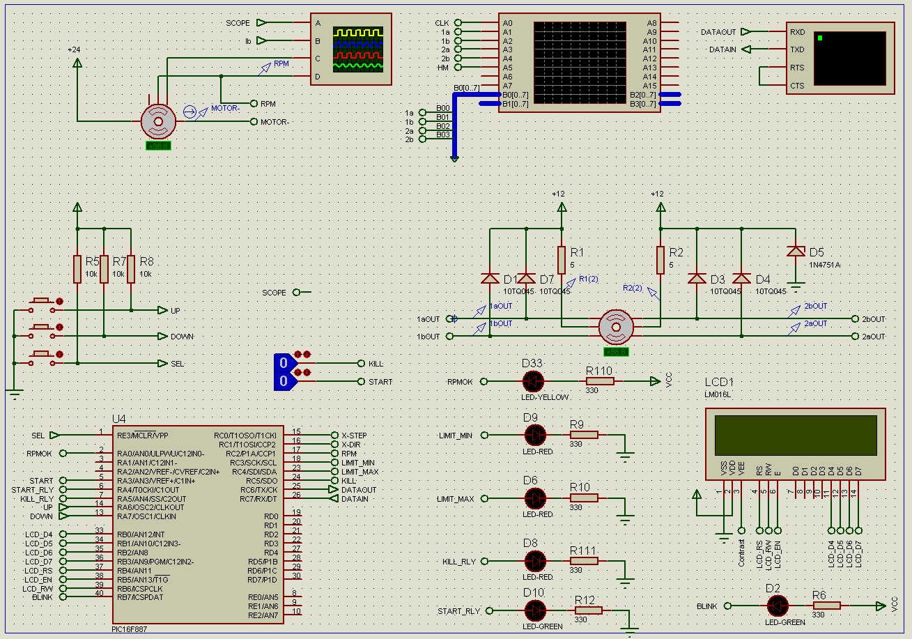
pic based pid motor control proteus simulation ii
The first schematic page contains the primary content of the design, while the second page features simulation support circuitry. The primary design controls the accessory relays and indicators. It also drives the control loop and adjusts the throttle control circuit....

c programming tutorial setup
For the other components, most of the necessary items should be available if any type of electronics work has been done, except for the programmer, RS232 chip, and PIC. To transfer information from the project to the PC, a USB...

eeprom
This PIC microcontroller EEPROM project saves temperature data from an LM35DZ IC to the internal long-term data storage of the PIC. The project is similar to the previous one, utilizing nearly the same hardware. It records temperature readings at regular...

binary clock
How to create a binary clock utilizing a PIC microcontroller with multiplexing to control an LED matrix.
To design a binary clock using a PIC microcontroller, the circuit will primarily consist of the microcontroller, an LED matrix, and multiplexing circuitry. The...