


LIRC receiver

Description: This circuit features a straightforward design. The RTS line of the serial port supplies power to a voltage regulator that stabilizes the output to 5 volts. A diode is incorporated to safeguard the serial port against reverse current. Additionally, a capacitor is used to maintain a consistent voltage level, with all ground connections tied to the GND line of the serial port. The data output from the IR receiver is linked to the DCD line of the serial port, along with a pull-up resistor connected to the power line.
The circuit operates with the RTS (Request to Send) line of the serial port providing the necessary power supply for the voltage regulator. This regulator is crucial for ensuring that the circuit operates at a stable 5 volts, which is essential for the reliable functioning of the connected components. The inclusion of a diode serves a protective function; it prevents any reverse current that could potentially damage the serial port by allowing current to flow in only one direction.
The capacitor plays a vital role in voltage stabilization by filtering any voltage fluctuations that may occur during operation. This ensures that the voltage remains constant, which is particularly important for sensitive electronic components that require a steady power supply. The grounding scheme is also critical; all grounds are connected to the GND line of the serial port, which helps in minimizing noise and ensuring a common reference point for the circuit.
Furthermore, the data output from the IR receiver is interfaced with the DCD (Data Carrier Detect) line of the serial port. This connection allows for the transmission of data signals from the IR receiver to the serial port. The addition of a pull-up resistor from the power line to the DCD line ensures that the line is held high when no data is being transmitted, which helps in maintaining a defined logic level and avoiding floating states that could lead to erratic behavior in the circuit.
Overall, this circuit is designed with simplicity and functionality in mind, effectively utilizing the components to ensure reliable communication and power management within the electronic system.The description of this circuit is rather simple. The RTS line of the serial port gives power to the voltage regulator which fixes it to 5 stable volts. A diode is there to protect the serial port from inverse current. The capacitor helps to keep a stable voltage; all the grounds are bound to the GND line of the serial port.
The data output of the IR receiver is connected to the DCD line of the serial port together with a pull-up resistor coming from the power line.
The circuit operates with the RTS (Request to Send) line of the serial port providing the necessary power supply for the voltage regulator. This regulator is crucial for ensuring that the circuit operates at a stable 5 volts, which is essential for the reliable functioning of the connected components. The inclusion of a diode serves a protective function; it prevents any reverse current that could potentially damage the serial port by allowing current to flow in only one direction.
The capacitor plays a vital role in voltage stabilization by filtering any voltage fluctuations that may occur during operation. This ensures that the voltage remains constant, which is particularly important for sensitive electronic components that require a steady power supply. The grounding scheme is also critical; all grounds are connected to the GND line of the serial port, which helps in minimizing noise and ensuring a common reference point for the circuit.
Furthermore, the data output from the IR receiver is interfaced with the DCD (Data Carrier Detect) line of the serial port. This connection allows for the transmission of data signals from the IR receiver to the serial port. The addition of a pull-up resistor from the power line to the DCD line ensures that the line is held high when no data is being transmitted, which helps in maintaining a defined logic level and avoiding floating states that could lead to erratic behavior in the circuit.
Overall, this circuit is designed with simplicity and functionality in mind, effectively utilizing the components to ensure reliable communication and power management within the electronic system.The description of this circuit is rather simple. The RTS line of the serial port gives power to the voltage regulator which fixes it to 5 stable volts. A diode is there to protect the serial port from inverse current. The capacitor helps to keep a stable voltage; all the grounds are bound to the GND line of the serial port.
The data output of the IR receiver is connected to the DCD line of the serial port together with a pull-up resistor coming from the power line.

Micropower Linear Voltage Regulator in the Battery Charger Circuit
The ADM666A application note provides a detailed explanation of a low-cost battery charger circuit, including maximum output voltage, charge termination voltage calculation, battery voltage level monitoring, and circuit efficiency optimization. The ADM666A utilizes an NPN transistor and a P-channel FET....

Heartbeat Sensor (Tranduscer)
This circuit consists of an infrared phototransistor and an infrared LED. The transducer operates on the principle of light reflection, specifically infrared light. The skin serves as a reflective surface for the infrared light, and the density of blood within...

Simple Low-Frequency Receiver
Using an NE602 heterodyne detector and U1 as an RF amplifier, this receiver tunes the middle portion of the low-frequency spectrum from 150 to 250 kHz. U2 is a loudspeaker amplifier.
The described circuit employs an NE602 integrated circuit as...

Simple Capacitor Tester
An LM3909 LED flasher functions as an oscillator, with the frequency determined by the capacitor connected to its terminals. The LED can be utilized to visually count frequency using a stopwatch for large capacitors (C > 500µF).
The LM3909 is an...

ELF MONITOR
The capacitor instrument is not intended for measuring the capacitance of capacitors; rather, it is designed to identify whether a capacitor is functional or defective, as well as to detect short circuits or open circuits. This functionality provides reliable quality...

18v power supply using lm7818
This power supply operates effectively to provide a stable 18V DC output with a maximum current of 1.5A. The circuit employs an LM7818 positive voltage regulator integrated circuit (IC), which includes several built-in features such as internal current limiting, short...

voltage regulator circuit with pass
This is a simple design for a voltage regulator circuit using a pass transistor. The design is built around the LM317T. The output current of the LM317T can be increased by incorporating an additional power transistor to share a portion...
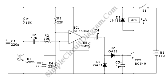
General Infrared Remote Controlled Relay
This relay circuit is controlled by nearly any type of infrared remote controller. The circuit operates under the assumption that most remote controllers utilize high-frequency signals.
The relay circuit described functions by receiving signals from an infrared (IR) remote control, which...

DIY computer infrared interface
A and B are two common contacts, along with an outline drawing and pin definitions. C refers to the shape of the infrared emission tube, including its pin definition and schematic symbol. CD4069 provides the pin definitions for the inverter...