


nikon
#IR remote
#Nikon D70s
#PIC 12F675
#shutter release
#camera control
#DIY
#photography
#microcontroller
#infrared
#remote trigger

Description: This document outlines the construction of an infrared (IR) remote shutter release for the Nikon D70s digital camera, which is also compatible with the Nikon D70 and potentially other models. The commercial equivalent of this device is the Nikon ML-L3 remote control. This project allows the user to trigger the camera shutter for self-portraits and long bulb exposures. It utilizes a Microchip PIC 12F675 microcontroller to generate the coded infrared signal necessary to activate the camera. The additional components required include a 3V coin battery, a switch, a resistor, and an IR LED. The total cost for the components is approximately $6. Acknowledgment is given to BigMike, who previously published a similar project using an AVR microcontroller and provided the IR code sequence needed for the Nikon camera. Although this version employs fewer components, BigMike's final product appears more professional. Caution is advised, as while the risk of damaging the camera is minimal, users should remain vigilant. The IR remote functions effectively up to about 10 feet (3 meters), with potential for increased range by using a more powerful battery or a smaller resistor to supply more power to the IR LED. However, it does not operate reliably at distances less than one inch, which complicates triggering shots when the user is not in the frame. The circuit diagram illustrates the project setup. The switch is used to power the microcontroller, which sends an output to the IR LED through a current-limiting resistor. A 330-ohm resistor was utilized, although this value can be adjusted based on the power supply and IR LED specifications. The microcontroller operates within a voltage range of 2V to 5.5V. Upon closing the switch, the microcontroller activates and transmits the coded IR signal to the camera before shutting down, conserving battery life compared to a standby mode. The electronics are housed within a 2xAA battery box sourced from a local electronic surplus store, which includes a power switch and a modified hole for the IR LED. The PIC 12F675 microcontroller features eight pins and operates on an internal 4MHz clock. In this configuration, six of the pins serve as general-purpose input/output (IO) pins, while the power pins accommodate a voltage range of 2.0V to 5.5V. The microcontroller can source up to 20mA from a pin, allowing direct powering of the LED through a current-limiting resistor, thereby reducing the total number of components required. The microcontroller is mounted in a socket for easy removal and reprogramming. All components, except for the battery and switch, are soldered onto a pre-drilled circuit board cut to fit within the AA battery compartment. The coin battery is secured using scotch tape for the power leads. The switch is repositioned in its original location within the battery box. The firmware for the microcontroller is straightforward; upon power application, the processor performs setup operations and initiates the transmission of the IR code to the camera. The IR sequence, decoded by BigMike, is modulated at 40kHz and consists of a specific pattern of pulses.
The circuit design for the IR remote shutter release is relatively simple yet effective. The Microchip PIC 12F675 microcontroller is the core of the system, providing the necessary control logic and signal generation capabilities. This microcontroller is chosen for its compact size, low power consumption, and sufficient processing power to handle the IR signal modulation.
The IR LED serves as the transmitter, sending the coded signals to the camera's IR receiver. The choice of a 330-ohm resistor is critical as it limits the current flowing through the LED, ensuring that it operates within safe parameters while still providing adequate brightness for reliable transmission. The circuit is powered by a 3V coin battery, which is a common and easily accessible power source for low-power applications.
The switch acts as a control mechanism, allowing the user to activate the circuit only when needed, thus extending battery life. Once the switch is engaged, the microcontroller executes its programmed sequence, sending the appropriate IR signal to the camera almost instantaneously. This design avoids the need for a standby mode, further conserving battery life.
The physical layout of the components is also considered for practical usability. The use of a battery box not only houses the components securely but also provides an ergonomic design for handling. The IR LED's placement is crucial, as it must have a clear line of sight to the camera's IR receiver for effective operation.
In summary, this IR remote shutter release project combines simplicity with functionality, providing a cost-effective solution for triggering Nikon cameras remotely. The careful selection of components and thoughtful design considerations contribute to the overall effectiveness and reliability of the system.This page describes building a IR remote shuttle release for the Nikon D70s digital camera (compatible with the Nikon D70 and possibly others). The equivalent commercial product is the Nikon ML-L3 remote control. It can be used to trigger the shutter for self portraits as well as for long `bulb` exposures. My project uses a Microchip PIC 12F675 mi croprocessor to produce the coded infra-red(IR) signal to trigger the camera. The only other parts required are a battery (I used a 3V coin battery), a switch, a resistor, and an IR LED. The result is a pretty cheap project (only about $6 for the parts). I would like to thank BigMike who published a similar project based on the AVR micro-controller and published the IR code sequence needed for the Nikon camera.
My version uses a few less parts but BigMike`s final result looks a lot more professional than mine. Warning: While the chances of damaging your camera with this project are slim, please be cautious. The following project worked for me but you are responsible for your actions and I make no guarantees of success or that you won`t hurt yourself or damage equipment as a result of the content of this page. It only works up to about 10ft/3m - this can probably be increased by getting a more powerful battery and/or using a smaller resistor (more power to the IR LED).
It also does not work reliably at less than an inch which makes it tricky to trigger shots where you (and the device) are not in the photo. In other words, it is hard to reach over the camera and trigger the shutter if you are doing a long exposure.
I have not investigated the possible causes for this - perhaps the IR LED I`m using has a narrow beam which does not reliably point at the IR detector on the camera The following diagram shows the circuit for the project. Basically, the switch is used to apply power to the microprocessor. An output from the microprocessor is connected to the IR LED via a current limiting resistor. I used a 330 ohm resister but this could be changed depending on power supply and on the IR LED used.
The microprocessor can operate on any voltage between 2V and 5. 5V. As soon as the switch is closed, the microprocessor powers up and sends out the coded IR signal to the camera, before powering off. The power up sequence is almost instantaneous and this method saves battery power over having the processor in stand-by waiting for a trigger and is simpler than having a separate on/off switch.
I placed the electronics inside a 2xAA-battery box that I found at a local electronic surplus store. Conveniently it came with a power switch and a little hole originally for the wires but that I used for the IR LED. The microprocessor, the PIC 12F675 from Microchip, has only 8 pins and runs off its internal 4Mhz clock.
In this configuration, other than the power pins (anything between 2. 0V and 5. 5V) all the remaining 6 pins are general purpose IO pins. Since the processor can source up to 20mA from a pin, I can power the LED directly from an output (via a current limiting resister). This has the advantage of allowing a very low parts count. I mounted the microprocessor in a socket so that I could easily remove the processor for re-programming if necessary.
All the components (except the battery and switch) were soldered on to a chunk of pre-drilled circuit board that I cut to fit within one of the cavities designed for the AA battery. Since I did not have a battery holder for the coin battery I used to power the device, I just scotch taped the power leads to the surface of the battery.
The switch was remounted in its original location in the battery box. The firmware for the microprocessor is pretty simple. When power is applied, the processor does a few set up operations and then begins sending out the IR code to the camera. The IR sequence was decoded by BigMike. The IR is modulated at 40kHz and consists of the following pulses: The tricky part
The circuit design for the IR remote shutter release is relatively simple yet effective. The Microchip PIC 12F675 microcontroller is the core of the system, providing the necessary control logic and signal generation capabilities. This microcontroller is chosen for its compact size, low power consumption, and sufficient processing power to handle the IR signal modulation.
The IR LED serves as the transmitter, sending the coded signals to the camera's IR receiver. The choice of a 330-ohm resistor is critical as it limits the current flowing through the LED, ensuring that it operates within safe parameters while still providing adequate brightness for reliable transmission. The circuit is powered by a 3V coin battery, which is a common and easily accessible power source for low-power applications.
The switch acts as a control mechanism, allowing the user to activate the circuit only when needed, thus extending battery life. Once the switch is engaged, the microcontroller executes its programmed sequence, sending the appropriate IR signal to the camera almost instantaneously. This design avoids the need for a standby mode, further conserving battery life.
The physical layout of the components is also considered for practical usability. The use of a battery box not only houses the components securely but also provides an ergonomic design for handling. The IR LED's placement is crucial, as it must have a clear line of sight to the camera's IR receiver for effective operation.
In summary, this IR remote shutter release project combines simplicity with functionality, providing a cost-effective solution for triggering Nikon cameras remotely. The careful selection of components and thoughtful design considerations contribute to the overall effectiveness and reliability of the system.This page describes building a IR remote shuttle release for the Nikon D70s digital camera (compatible with the Nikon D70 and possibly others). The equivalent commercial product is the Nikon ML-L3 remote control. It can be used to trigger the shutter for self portraits as well as for long `bulb` exposures. My project uses a Microchip PIC 12F675 mi croprocessor to produce the coded infra-red(IR) signal to trigger the camera. The only other parts required are a battery (I used a 3V coin battery), a switch, a resistor, and an IR LED. The result is a pretty cheap project (only about $6 for the parts). I would like to thank BigMike who published a similar project based on the AVR micro-controller and published the IR code sequence needed for the Nikon camera.
My version uses a few less parts but BigMike`s final result looks a lot more professional than mine. Warning: While the chances of damaging your camera with this project are slim, please be cautious. The following project worked for me but you are responsible for your actions and I make no guarantees of success or that you won`t hurt yourself or damage equipment as a result of the content of this page. It only works up to about 10ft/3m - this can probably be increased by getting a more powerful battery and/or using a smaller resistor (more power to the IR LED).
It also does not work reliably at less than an inch which makes it tricky to trigger shots where you (and the device) are not in the photo. In other words, it is hard to reach over the camera and trigger the shutter if you are doing a long exposure.
I have not investigated the possible causes for this - perhaps the IR LED I`m using has a narrow beam which does not reliably point at the IR detector on the camera The following diagram shows the circuit for the project. Basically, the switch is used to apply power to the microprocessor. An output from the microprocessor is connected to the IR LED via a current limiting resistor. I used a 330 ohm resister but this could be changed depending on power supply and on the IR LED used.
The microprocessor can operate on any voltage between 2V and 5. 5V. As soon as the switch is closed, the microprocessor powers up and sends out the coded IR signal to the camera, before powering off. The power up sequence is almost instantaneous and this method saves battery power over having the processor in stand-by waiting for a trigger and is simpler than having a separate on/off switch.
I placed the electronics inside a 2xAA-battery box that I found at a local electronic surplus store. Conveniently it came with a power switch and a little hole originally for the wires but that I used for the IR LED. The microprocessor, the PIC 12F675 from Microchip, has only 8 pins and runs off its internal 4Mhz clock.
In this configuration, other than the power pins (anything between 2. 0V and 5. 5V) all the remaining 6 pins are general purpose IO pins. Since the processor can source up to 20mA from a pin, I can power the LED directly from an output (via a current limiting resister). This has the advantage of allowing a very low parts count. I mounted the microprocessor in a socket so that I could easily remove the processor for re-programming if necessary.
All the components (except the battery and switch) were soldered on to a chunk of pre-drilled circuit board that I cut to fit within one of the cavities designed for the AA battery. Since I did not have a battery holder for the coin battery I used to power the device, I just scotch taped the power leads to the surface of the battery.
The switch was remounted in its original location in the battery box. The firmware for the microprocessor is pretty simple. When power is applied, the processor does a few set up operations and then begins sending out the IR code to the camera. The IR sequence was decoded by BigMike. The IR is modulated at 40kHz and consists of the following pulses: The tricky part

Infrared receiver
The circuit consists of Q1, a phototransistor that responds to an intensity of amplitude-modulated infrared light source, and a three-stage, high-gain audio amplifier. Transformer T1 is utilized to match the output impedance of the receiver to modern low-impedance (low-Z) headphones....

The Infrared Demodulation Circuit Using Low-Noise Amplifier
This circuit employs an HgCdTe demodulation device that can be cooled to 77K using liquid nitrogen. It utilizes a constant current bias for the demodulation device, which is connected to the input port. The voltage amplification factor is 200, and...

IR remote control for PC
This simple circuit allows you to record any IR remote control signal on your PC, and then play it back. This is particularly useful if you want to control appliances such as TVs, VCRs, CDs etc. from your computer. The...

Ir Remote Extender
This circuit can be utilized to operate a VCR or CD player from a different room. It functions as an infrared signal repeater. The signal from the remote control is received and retransmitted through wires to an infrared LED. The...

Direct infrared remote control switch circuit diagram composed of LS-2
The LS-2 remote control switch infrared sensor module is similar to the LS-18 but functions as a reflector. The LS-2 pin diagram and internal block diagram provide insights into its electrical parameters. The operating voltage for the LS-2 remote control...

Infrared Remote Extender
This project originated from the necessity to remotely control audio-visual equipment located inside cupboards. RF-based commercial units such as those used for...
The project aims to develop a system that enables the remote operation of audio-visual devices housed within enclosed spaces,...

infrared receiver ir rx output waveform
In the image above, Oscium's iMSO-104 oscilloscope is measuring the output waveform of an infrared receiver (IR Rx). The iPad and iMSO serve as the oscilloscope to measure the receiver's output signal as the alignment between the transmitter and receiver...

Infrared Transmitter-Receiver with 555
The infrared transmitter and receiver circuit depicted in the schematic diagram can function as a remote control system. The transmitter operates as an oscillator circuit, with the frequency adjustable through the R1 potentiometer (or trimmer pot). This oscillation ensures that...
Help with a schematic please
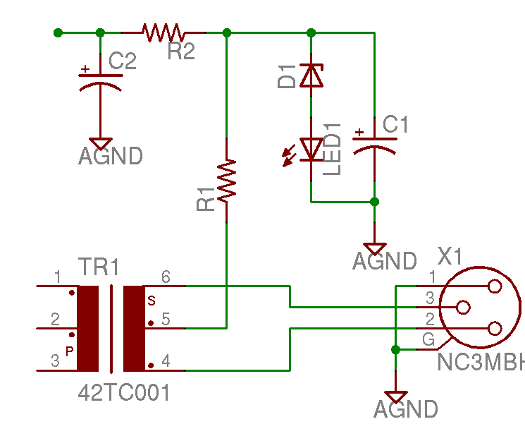
A project is underway to construct the CountryHick DI as illustrated on DIYFactory, incorporating a few minor modifications. The final design aims to be a 1U unit with four inputs.
The CountryHick DI (Direct Injection) box is a crucial tool in...