


Simply by remote control law circuit diagram
#TV signal
#satellite receiver
#living room
#bedroom
#television
#receiver
#convenience
#signal distribution

Description: The receiver provides two TV signals, one for the living room and another for the bedroom, along with a satellite receiver. Watching television in the bedroom is convenient in Taiwan; however, when watching television in the living room, it can be troublesome to carry the remote control back and forth between rooms to change settings. To simplify viewing, a remote infrared control device has been designed, which has proven effective in practice. The principles and production process of the circuit are outlined as follows: The circuit utilizes an optional infrared receiver, a universal integrated infrared receiver, which is shaped as depicted. The infrared remote control signal is received by the infrared receiver (REM V1, V2), which activates the infrared emission control. The setup includes a coaxial cable and infrared emitting diodes connected appropriately to the satellite receiver located in the front nook of the bedroom. With this device, users can conveniently hold the remote control in the living room and select the desired TV program ratings without the need to move to the bedroom.
The circuit design for the infrared remote control system comprises several key components that facilitate seamless operation between two television sets and a satellite receiver. The universal infrared receiver (REM) is the core of this system, capable of detecting signals from standard remote controls. Upon receiving an infrared signal, the receiver activates output control signals that drive an infrared LED emitter. This LED emits infrared light that can be directed towards the satellite receiver located in the bedroom.
The connection between the living room and bedroom is established using coaxial cables, ensuring minimal signal loss and interference. The infrared LEDs should be positioned strategically to ensure that the emitted signals can effectively reach the satellite receiver, which is crucial for reliable operation. The circuit also includes necessary resistors and capacitors to stabilize the power supply to the infrared components and ensure consistent performance.
In terms of power supply, the circuit can be powered using a standard DC power adapter, which should be connected to the infrared receiver and LED emitter. It is essential to select components that operate efficiently at the given voltage to prevent overheating and ensure longevity.
Overall, this infrared remote control system significantly enhances the viewing experience by allowing users to operate their television sets from a distance without the inconvenience of moving between rooms. The design is user-friendly, and the implementation of the circuit is straightforward, making it an excellent solution for households with multiple televisions.The receiver provides two TV signal, a TV in the living room, another TV in the bedroom, along with a satellite receiver. Watching television in the bedroom for Taiwan convenient, but when watching television in the living room,
for Taiwan to bother, to be holding the remote control to the bedroom to change my desk, then back to the living room watching a program, a lot of trouble. In order to facilitate viewing, design a remote infrared remote control device, the actual use to good effect.
Principles and production process of the circuit is as follows: REM optional infrared receiver universal integrated infrared receiver, the shape as shown, infrared remote control signal received by REM V1, V2, zoom promote infrared emission control work. The figure outside the dotted line in the living room, with a coaxial cable and infrared emitting diodes after receiving portion is connected to the appropriate place in the front bedroom nook satellite receiver.
With this device, you can easily hold the remote control in the living room to see the need to choose the TV program ratings.
The circuit design for the infrared remote control system comprises several key components that facilitate seamless operation between two television sets and a satellite receiver. The universal infrared receiver (REM) is the core of this system, capable of detecting signals from standard remote controls. Upon receiving an infrared signal, the receiver activates output control signals that drive an infrared LED emitter. This LED emits infrared light that can be directed towards the satellite receiver located in the bedroom.
The connection between the living room and bedroom is established using coaxial cables, ensuring minimal signal loss and interference. The infrared LEDs should be positioned strategically to ensure that the emitted signals can effectively reach the satellite receiver, which is crucial for reliable operation. The circuit also includes necessary resistors and capacitors to stabilize the power supply to the infrared components and ensure consistent performance.
In terms of power supply, the circuit can be powered using a standard DC power adapter, which should be connected to the infrared receiver and LED emitter. It is essential to select components that operate efficiently at the given voltage to prevent overheating and ensure longevity.
Overall, this infrared remote control system significantly enhances the viewing experience by allowing users to operate their television sets from a distance without the inconvenience of moving between rooms. The design is user-friendly, and the implementation of the circuit is straightforward, making it an excellent solution for households with multiple televisions.The receiver provides two TV signal, a TV in the living room, another TV in the bedroom, along with a satellite receiver. Watching television in the bedroom for Taiwan convenient, but when watching television in the living room,
for Taiwan to bother, to be holding the remote control to the bedroom to change my desk, then back to the living room watching a program, a lot of trouble. In order to facilitate viewing, design a remote infrared remote control device, the actual use to good effect.
Principles and production process of the circuit is as follows: REM optional infrared receiver universal integrated infrared receiver, the shape as shown, infrared remote control signal received by REM V1, V2, zoom promote infrared emission control work. The figure outside the dotted line in the living room, with a coaxial cable and infrared emitting diodes after receiving portion is connected to the appropriate place in the front bedroom nook satellite receiver.
With this device, you can easily hold the remote control in the living room to see the need to choose the TV program ratings.
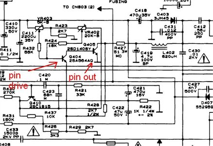
I have a Teac ctm805sr tv suffering pincushion
The task involves repairing a television, specifically identifying the area on the schematic related to the pincushion circuit, which appears to be the primary issue. Initial inspections revealed some dry joints and poor soldering that were addressed, but these repairs...

High Performance Regen Receiver
A new high-performance regenerative receiver is available as a kit. The inclusion of an innovative regenerative detector circuit enhances sensitivity and overall performance.
The regenerative receiver kit is designed to provide users with a high-quality radio frequency (RF) reception experience. The...

simple booster tv schematic diagram
This circuit is designed to enhance RF signals from a television antenna operating at UHF frequencies in the range of 450-800 MHz. It provides a gain of approximately 10 dB, making it suitable for boosting weak TV signals. The tuned...
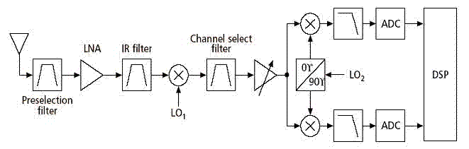
receiver architectures
Various architectures of receivers have been proposed in literature, but the most popular architectures among them, such as Heterodyne, Homodyne, Wideband-IF, and Low-IF, are presented here.
The Heterodyne receiver architecture utilizes two frequencies: the incoming radio frequency (RF) signal and a...

circuit satellite receiver
The Dish Network 322 Satellite Receiver enables television viewing of two distinct programs in two separate locations. This is a schematic block diagram illustrating an exemplary circuit logic diagram. The receiver is capable of predicting the elevation angle for each...

Simple Direct Conversion Receiver
A low-cost continuous wave (CW) superheterodyne receiver operates with a 4.00 MHz intermediate frequency. While there is no automatic gain control (AGC) or RF gain control, the receiver demonstrates good large signal handling capabilities. The design incorporates six bipolar transistors...

A simple tuned radio frequency receiver
This simple tuned radio frequency receiver was designed and constructed in the mid-1990s. The receiver was tested under urban and field conditions, in varying temperatures. This straightforward circuit exhibits high sensitivity, good sound quality, and reliability. A signal received by...

Amateur Television Transmitter
Although the unit was designed for 2 W operation, the Q6 and Q7 stages and their associated components can be omitted. Approximately 1 to 30 mW of RF can be obtained by link coupling to L9. A complete set of...

MK414 SW Receiver
The original data sheet for the MK414 indicates that the maximum working frequency is approximately 4 MHz. SW transmissions are sufficiently strong that this receiver can effectively operate with signals up to about 6 or 7 MHz. A 10k resistor...