


The Autonomous Drifter Circuit
#RC car
#transmitter
#PWM
#digital
#switches
#encoder
#remote control
#wireless
#automotive
#communication

Description: The first schematic examined is the base schematic of the transmitter without any modifications. The RC car's transmitter circuit consists of two halves. One side (on the left) is predominantly digital. When a switch (1-4) is pressed, IC1 becomes active, producing an encoded PWM (pulse width modulation) signal. The transmitter requires a 9V battery for operation. However, the circuit can function with a +5V supply from the LM7805, as long as the integrated circuit (IC) has sufficient power. The switches control the car's movements: forward, backward, left, or right. It is important to observe the connections of the switches to ground; when a switch is pressed, it connects to ground. These connections are critical for enabling the microcontroller to manage the transmitter's output. The crystal labeled X1 is a 27MHz oscillator, generating the frequency signal to which the IC1 output will be modulated. Signal mixing occurs just after the R4 resistor, approaching the output transistor (TR1). The final output is relatively low power, in the milliwatt range. While understanding this circuit is not essential for creating the project, it is worth noting that IC1 is unidentified; its exact nature is obscured by a coating. It is speculated that it may be a microcontroller or encoder, as it outputs an encoded PWM signal for modulation. Switching the 3-way switch on the transmitter alters the encoding, allowing control of three cars simultaneously.
The RC car transmitter circuit is a fundamental example of combining digital and analog components to achieve wireless control. The two halves of the circuit serve distinct yet complementary roles, with the left side focusing on digital signal processing. The pressing of switches 1-4 activates IC1, which encodes the user input into a PWM signal. This encoding is essential for ensuring that the transmitter can communicate effectively with the receiver in the RC car.
The choice of power supply is also notable; while the design originally calls for a 9V battery, the use of a +5V supply from an LM7805 voltage regulator demonstrates a practical approach to circuit design, allowing for lower power consumption while maintaining functionality. This decision reflects a common practice in electronics where efficiency and simplicity are prioritized.
The switches' connection to ground is a critical aspect of the circuit operation. When a switch is pressed, it completes the circuit to ground, signaling to the microcontroller the desired action. This connection allows for real-time control of the car's movements, emphasizing the importance of understanding how user inputs translate into electrical signals.
The 27MHz oscillator (X1) plays a pivotal role in frequency modulation. This oscillator generates a stable frequency that is necessary for the RF transmission. The output signal, modulated by this frequency, is then processed through R4, which likely serves as a filtering component to ensure that only the desired frequency components are passed to the output transistor (TR1). The transistor amplifies the signal, allowing it to be transmitted over a distance.
The low power output indicates that the circuit is designed for efficiency, suitable for battery-operated devices like RC cars. The speculation surrounding IC1 highlights the challenges often faced in reverse-engineering circuits, particularly when components are obscured. Nevertheless, the function of IC1 as a PWM encoder is crucial for the operation of the transmitter. The ability to switch encoding modes via a 3-way switch illustrates a thoughtful design choice, enabling multiple vehicles to be controlled without interference, showcasing the ingenuity behind the circuit's design.The first schematic that we`ll look at is the base schematic of the transmitter without any modification. The RC car`s transmitter circuit has two halves to it. One side (on the left) is pretty much all digital. When a switch(1-4) is pressed, IC1 becomes active and an encoded PWM (pulse with modulation) signal is output.
The packaging for the tr ansmitter required a 9v battery to be used. Since we`re wise in the ways of circuits and see that this circuit can operate as long as the IC has enough power to function, we`ll just use +5v off the LM7805. These switches control what the car does. Move forward, backward, left or right. Look carefully at where the switches are connected to ground. When the switch is pressed ground is connected. These are the key spots to making the microcontroller able to control what the transmitter outputs. We`ll see what connects to them on the next schematic. The crystal labeled X1 is actually a 27MHz oscillator. This will generate the frequency signal that the IC1 output will be modulated to (Toy RC cars are allowed to be on either 27MHz or 49 MHz frequency channels).
The signal mixing occurs directly after the R4 Resistor approaching the output transistor (TR1). Output finally occurs after all that and is relatively low power (mW range). Understanding this circuit is not crucial to creating this project. Just a small note. IC1 is unknown. What exactly it is, is not directly clear as there is a nice glab of black crap right over it. My best guess is it is either a microcontroller or encoder as it outputs an encoded PWM signal to be modulated. If you switch the 3-way switch on the transmitter the encoding changes (this is to allow 3 cars to be able to be controlled simultaneously).
The RC car transmitter circuit is a fundamental example of combining digital and analog components to achieve wireless control. The two halves of the circuit serve distinct yet complementary roles, with the left side focusing on digital signal processing. The pressing of switches 1-4 activates IC1, which encodes the user input into a PWM signal. This encoding is essential for ensuring that the transmitter can communicate effectively with the receiver in the RC car.
The choice of power supply is also notable; while the design originally calls for a 9V battery, the use of a +5V supply from an LM7805 voltage regulator demonstrates a practical approach to circuit design, allowing for lower power consumption while maintaining functionality. This decision reflects a common practice in electronics where efficiency and simplicity are prioritized.
The switches' connection to ground is a critical aspect of the circuit operation. When a switch is pressed, it completes the circuit to ground, signaling to the microcontroller the desired action. This connection allows for real-time control of the car's movements, emphasizing the importance of understanding how user inputs translate into electrical signals.
The 27MHz oscillator (X1) plays a pivotal role in frequency modulation. This oscillator generates a stable frequency that is necessary for the RF transmission. The output signal, modulated by this frequency, is then processed through R4, which likely serves as a filtering component to ensure that only the desired frequency components are passed to the output transistor (TR1). The transistor amplifies the signal, allowing it to be transmitted over a distance.
The low power output indicates that the circuit is designed for efficiency, suitable for battery-operated devices like RC cars. The speculation surrounding IC1 highlights the challenges often faced in reverse-engineering circuits, particularly when components are obscured. Nevertheless, the function of IC1 as a PWM encoder is crucial for the operation of the transmitter. The ability to switch encoding modes via a 3-way switch illustrates a thoughtful design choice, enabling multiple vehicles to be controlled without interference, showcasing the ingenuity behind the circuit's design.The first schematic that we`ll look at is the base schematic of the transmitter without any modification. The RC car`s transmitter circuit has two halves to it. One side (on the left) is pretty much all digital. When a switch(1-4) is pressed, IC1 becomes active and an encoded PWM (pulse with modulation) signal is output.
The packaging for the tr ansmitter required a 9v battery to be used. Since we`re wise in the ways of circuits and see that this circuit can operate as long as the IC has enough power to function, we`ll just use +5v off the LM7805. These switches control what the car does. Move forward, backward, left or right. Look carefully at where the switches are connected to ground. When the switch is pressed ground is connected. These are the key spots to making the microcontroller able to control what the transmitter outputs. We`ll see what connects to them on the next schematic. The crystal labeled X1 is actually a 27MHz oscillator. This will generate the frequency signal that the IC1 output will be modulated to (Toy RC cars are allowed to be on either 27MHz or 49 MHz frequency channels).
The signal mixing occurs directly after the R4 Resistor approaching the output transistor (TR1). Output finally occurs after all that and is relatively low power (mW range). Understanding this circuit is not crucial to creating this project. Just a small note. IC1 is unknown. What exactly it is, is not directly clear as there is a nice glab of black crap right over it. My best guess is it is either a microcontroller or encoder as it outputs an encoded PWM signal to be modulated. If you switch the 3-way switch on the transmitter the encoding changes (this is to allow 3 cars to be able to be controlled simultaneously).

Wireless Color Sensor
Close to human perception and stable color sensing is a pervasive challenge encountered in various disciplines, such as machine vision for classification and recognition, as well as in intelligent systems like smart illumination systems in home or workplace environments. In...
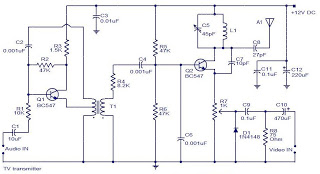
televition transmitter
The camera is oriented to look out the side of the rocket during launch and downward during descent on the parachute. An optional external mirror can be added to enable the camera to look down during lift-off. The transmitter antenna,...

Wireless/Wii Hack for SNES and NES Controllers
The NES version of this modification closely resembles the SNES version, and it is advisable to review that article first for a general understanding of the assembly of these controllers. The primary component required is an original NES controller, which...
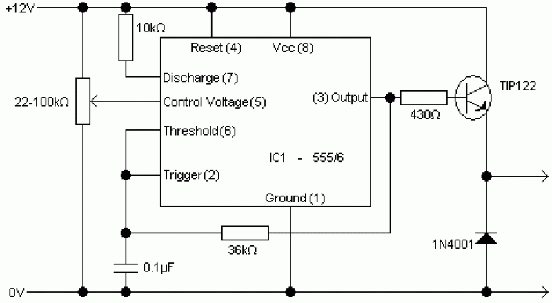
PWM Motor Control circuit
This controller is designed primarily for controlling model trains and can deliver approximately 12-15 Volts, though it operates effectively at voltages as low as 3V, including a 6V supply for certain accessories. The maximum output current is theoretically around 5...

Emergency Egg Locator Beacon (EELB)
This project was inspired by a circuit that a friend, Simon Field, showcased. He built a simple transmitter circuit using a 1 MHz "can" oscillator and a serial connector. In his circuit, he utilized a computer to turn the transmitter...

PWM Dimmer/Motor Speed Controller
This project addresses the need for a simple circuit that can dim LED lights or control the speed of 12V DC motors. The circuit utilizes Pulse Width Modulation (PWM) to manage the effective or average current flowing through an LED...

PWM Modulator Using Op-Amp
This is a simple PWM modulator circuit. Comparing the message signal to a ramp or triangular waveform is the simplest way to produce a PWM signal. When the...
The PWM (Pulse Width Modulation) modulator circuit operates by comparing a modulating signal,...

Home Automation through Cellphone Keying
This project was developed during a Bachelor of Engineering course to enable remote control of lights and other appliances within a room. The objective was to address the common issue of forgetting to turn off devices such as fans or...

PWM Modulator
If one has considered experimenting with pulse-width modulation, this circuit serves as an excellent starting point. The design prioritizes simplicity by utilizing a dual 555 timer, making the assembly straightforward. A small PCB has been created for this purpose, facilitating...