


Tiny RC Cars - Transmitter and Charger

Description: The transmitter runs on only 3V whereas most others run on more voltage. This dirt cheap item uses non-adjustable inductors so it is not possible to tweak for higher output. The common TX2B chip is manufactured by HIGHLAND (SHENZHEN) ELECTRONICS CO LTD and by REALTEK SEMICONDUCTOR CORP and others. More: Datasheets are available on the web but I don`t remember where now. Here is the circuit at 27 and 49 MHz:
The described transmitter circuit operates at a low voltage of 3V, which is notably lower than many comparable devices that require higher voltage levels for operation. This characteristic makes the transmitter an economical option for various applications. The use of non-adjustable inductors indicates a fixed design, which limits the ability to modify the output frequency or power levels. This can be a significant consideration for users needing flexibility in their RF designs.
The TX2B chip, a common component in this circuit, is produced by HIGHLAND (SHENZHEN) ELECTRONICS CO LTD and REALTEK SEMICONDUCTOR CORP, among others. This chip is typically used in low-power RF transmitter applications, making it suitable for short-range communication systems such as remote controls, wireless microphones, and other similar devices.
The circuit operates at two specified frequencies, 27 MHz and 49 MHz. These frequency bands are often utilized for various consumer electronics and can be subject to regulations regarding transmission power and range. The design of the circuit likely includes essential components such as capacitors, resistors, and possibly a crystal oscillator to stabilize the frequency output.
For practical implementation, the layout should ensure minimal interference and optimal performance. Proper grounding and shielding techniques should be employed to mitigate noise and enhance signal integrity. The circuit may also include a simple antenna design, which is crucial for effective transmission and reception of the RF signals.
Datasheets for the TX2B chip and other components may be available online, providing detailed specifications, pin configurations, and suggested application circuits, which can be instrumental for engineers looking to implement or modify this transmitter circuit for specific use cases.The transmitter runs on only 3V whereas most others run on more voltage. This dirt cheap item uses non-adjustable inductors so it is not possible to tweak for higher output. The common TX2B chip is manufactured by HIGHLAND (SHENZHEN) ELECTRONICS CO LTD and by REALTEK SEMICONDUCTOR CORP and others. Datasheets are available on the web but I don`t remember where now. Here is the circuit at 27 and 49 MHz:
The described transmitter circuit operates at a low voltage of 3V, which is notably lower than many comparable devices that require higher voltage levels for operation. This characteristic makes the transmitter an economical option for various applications. The use of non-adjustable inductors indicates a fixed design, which limits the ability to modify the output frequency or power levels. This can be a significant consideration for users needing flexibility in their RF designs.
The TX2B chip, a common component in this circuit, is produced by HIGHLAND (SHENZHEN) ELECTRONICS CO LTD and REALTEK SEMICONDUCTOR CORP, among others. This chip is typically used in low-power RF transmitter applications, making it suitable for short-range communication systems such as remote controls, wireless microphones, and other similar devices.
The circuit operates at two specified frequencies, 27 MHz and 49 MHz. These frequency bands are often utilized for various consumer electronics and can be subject to regulations regarding transmission power and range. The design of the circuit likely includes essential components such as capacitors, resistors, and possibly a crystal oscillator to stabilize the frequency output.
For practical implementation, the layout should ensure minimal interference and optimal performance. Proper grounding and shielding techniques should be employed to mitigate noise and enhance signal integrity. The circuit may also include a simple antenna design, which is crucial for effective transmission and reception of the RF signals.
Datasheets for the TX2B chip and other components may be available online, providing detailed specifications, pin configurations, and suggested application circuits, which can be instrumental for engineers looking to implement or modify this transmitter circuit for specific use cases.The transmitter runs on only 3V whereas most others run on more voltage. This dirt cheap item uses non-adjustable inductors so it is not possible to tweak for higher output. The common TX2B chip is manufactured by HIGHLAND (SHENZHEN) ELECTRONICS CO LTD and by REALTEK SEMICONDUCTOR CORP and others. Datasheets are available on the web but I don`t remember where now. Here is the circuit at 27 and 49 MHz:

Telegraph Transmitter in the Pilot Radios Radio Design magazine 1930s
The TPTG transmitter has been transformed into a modern TNT model. This transmitter can utilize the existing K-111 power pack for both the transmitter and receiver, eliminating the need for a separate power supply unit. Building this compact transmitter allows...

transmitter circuit diagram
Clearly indicate on the circuit diagram each type and size of the components. There is a need for assistance in designing a low power FM transmitter circuit, specifically using the BA1404 FM transmitter with a center frequency of 79W and...

Atv Jr Transmitter 440Mhz Circuit
This low-power video transmitter is designed for remote control (R/C) applications, surveillance, or amateur radio purposes. It utilizes seven transistors within a crystal oscillator-multiplier RF power amplifier chain, along with a high-level video modulator. A supply voltage of 9 to...

TV transmitter circuit using only 2 transistors operates from 12V
A simple two-transistor TV transmitter circuit that operates from 12V. It is compatible with PAL B and PAL G systems.
The described circuit utilizes two transistors to create a basic television transmission system capable of operating on a 12V power supply....

Transmitter-oscilloscope coupler for CB signals
To display an RF signal, connect LI to the transmitter and points A and B to the vertical plates of the oscilloscope. Adjust LI for minimum SWR and C3 for the desired trace height on the CRT. More: L2 consists...
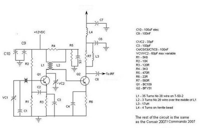
Corsair and Commando TXs
This document provides information about the Corsair and Commando Transmitters designed by Dave Martin of WNKR. It outlines the construction of each transmitter and includes examples created by others. The circuit diagram presented illustrates the initial two stages of a...

Precision QRP Transmitter
This compact transmitter is suitable for less demanding Doppler propagation measurements. It is designed for operation on the 80m band but can be easily adapted for the 40m or 20m bands. The output power is approximately 500mW of unmodulated carrier,...

50W Tube-Valve SW transmitter
This transmitter operates in the shortwave range from 6 MHz to 22 MHz. Coil L1 serves as the shortwave oscillating coil for the 6SA7 vacuum tube and is commercially available. Capacitor C1 is a variable capacitor with a capacitance range...

Carrier-current-audio-transmitter
The choice between AM, narrowband FM (less than 15 kHz), or wideband FM (greater than 30 kHz) is determined by the specific application. FM is preferable for music transmission due to its superior noise immunity. For speech or other non-critical...