


TL163 IC For Ultrasonic Remote Control
#TL163 IC
#ultrasonic
#remote control
#detector
#high-gain amplifier
#low-frequency
#circuit diagram

Description: The following circuit illustrates the TL163 integrated circuit (IC) used in an ultrasonic remote control circuit diagram. Features include a detector, high-gain amplifier, and low-frequency response.
The TL163 IC is designed to facilitate ultrasonic signal processing, making it suitable for applications such as remote control systems. The circuit typically comprises several key components: the TL163 IC itself, which integrates a high-gain amplifier and a detector to process incoming ultrasonic signals.
In the schematic, the power supply is connected to the VCC pin of the TL163, ensuring that the IC operates within its specified voltage range. The input pin receives the ultrasonic signals, which are often generated by a transmitter circuit. The TL163 amplifies these signals using its internal high-gain amplifier, which is critical for distinguishing between the desired ultrasonic signals and background noise.
The detector feature of the TL163 is responsible for identifying the presence of the ultrasonic signal. When the signal is detected, the output pin of the IC can be configured to drive additional circuitry, such as a microcontroller or a relay, to execute specific commands based on the received signal.
The circuit may also include passive components such as resistors and capacitors, which are used to set the gain of the amplifier and filter the signals to ensure optimal performance. Additionally, the layout of the circuit should minimize interference and ensure that the ultrasonic signals are effectively transmitted and received.
Overall, the TL163-based ultrasonic remote control circuit provides a robust solution for wireless control applications, leveraging the advantages of ultrasonic frequencies for reliable signal transmission.The following circuit shows about TL163 IC For Ultrasonic Remote Control Circuit Diagram. Features:detector, high-gain amplifier, low-frequency .
The TL163 IC is designed to facilitate ultrasonic signal processing, making it suitable for applications such as remote control systems. The circuit typically comprises several key components: the TL163 IC itself, which integrates a high-gain amplifier and a detector to process incoming ultrasonic signals.
In the schematic, the power supply is connected to the VCC pin of the TL163, ensuring that the IC operates within its specified voltage range. The input pin receives the ultrasonic signals, which are often generated by a transmitter circuit. The TL163 amplifies these signals using its internal high-gain amplifier, which is critical for distinguishing between the desired ultrasonic signals and background noise.
The detector feature of the TL163 is responsible for identifying the presence of the ultrasonic signal. When the signal is detected, the output pin of the IC can be configured to drive additional circuitry, such as a microcontroller or a relay, to execute specific commands based on the received signal.
The circuit may also include passive components such as resistors and capacitors, which are used to set the gain of the amplifier and filter the signals to ensure optimal performance. Additionally, the layout of the circuit should minimize interference and ensure that the ultrasonic signals are effectively transmitted and received.
Overall, the TL163-based ultrasonic remote control circuit provides a robust solution for wireless control applications, leveraging the advantages of ultrasonic frequencies for reliable signal transmission.The following circuit shows about TL163 IC For Ultrasonic Remote Control Circuit Diagram. Features:detector, high-gain amplifier, low-frequency .

Ultrasonic Pest Repeller
A higher-end version of the same device, featuring additional user-selectable settings to enable both audible and ultrasonic output, enhancing its effectiveness against animals.
The described device is an advanced electronic system designed to produce sound waves at both audible and ultrasonic...
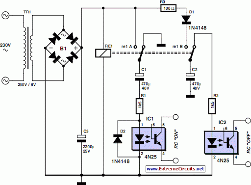
remote control mains switch
As the only electronics engineer in the family and circle of friends, it is sometimes challenging to decline requests for assistance. Recently, a friendly elderly lady in a retirement home sought help regarding her lighting situation. In her room, the...

Low-frequency-multivibrator
This circuit utilizes one half of the CA3290 BiMOS dual voltage comparator as a conventional multivibrator. The second half ensures frequency stability against the effects of output loading. Large values of the timing resistor, Rl, guarantee long time delays when...

Ultrasonic Range & Imager
The electronic schematic of the homebuilt SONAR utilizes a single piezoelectric transducer for both transmission and reception. This transducer is switched from transmission (TX) to reception (RX) using four 4016 switches. A high-gain amplifier stage and rectifier convert the received...

ultrasonic transmitter
This section provides step-by-step instructions along with images for constructing an Ultrasonic Proximity Transmitter. Due to the simplicity of the circuit, only a schematic for the sensor is presented here. The objective of this tutorial is to assist others in...
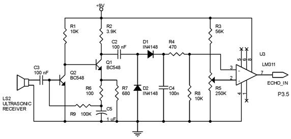
ultrasonic distance measurer
Techniques for an echo sounder used to measure ocean depth can be implemented with an ultrasonic distance measuring device. This device uses a circuit similar to the one described in the previous article, which includes a series of ultrasonic transmitter...

Ultrasonic-pulsed-pest-controller
IC2 is a stable oscillator whose frequency and pulse width are determined by the values of R4, R5, R6, and C4. R4 is adjustable for precise frequency setting. The output from IC2 is at pin 3, which is capacitively coupled...

Cat / Dog Detector
This can be used to control entry on a Cat or Dog Door. NOTE: There may be some changes and improvements coming. However, this circuit does work and you can build it as shown. The PCB shown below is available...

Ultrasonic switch
The transmitter section of the circuit is built around IC1 (NE 555), which is configured as an astable multivibrator operating at 40 kHz. The output from IC1 is amplified by a complementary pair of transistors (Q1 and Q2) and transmitted...