


Analog Compensation Circuit for PT100 RTD Temperature Sensor
#PT100
#RTD
#temperature sensor
#analog compensation
#linearization
#thermistor
#measurement
#precision
#signal conditioning
#sensor interface

Description: There are digital and analog methods that can be used to compensate for the nonlinearity of a PT100 RTD. Digital linearization can be implemented through various techniques.
Compensation for the nonlinearity of a PT100 RTD (Resistance Temperature Detector) is essential for achieving accurate temperature measurements. The PT100 RTD exhibits a nonlinear response to temperature changes, which can lead to measurement errors if not properly addressed.
Digital methods for linearization often involve the use of microcontrollers or digital signal processors (DSPs) that apply algorithms to correct the nonlinear response. These algorithms can include polynomial fitting, lookup tables, or spline interpolation to map the nonlinear characteristics of the PT100 to a linear output. The implementation typically requires an analog-to-digital converter (ADC) to sample the RTD output, followed by processing the data using the chosen algorithm, and finally outputting the corrected digital signal.
Analog methods may involve the use of operational amplifiers (op-amps) configured in specific arrangements to create a linear output based on the RTD resistance. This can include using resistor networks or feedback loops to shape the response curve. The choice between digital and analog methods depends on the specific application requirements, including factors such as cost, complexity, and desired accuracy.
In summary, both digital and analog techniques are viable for compensating the nonlinearity of PT100 RTDs, with each method offering distinct advantages and considerations for implementation.There are some digital and analog that can be used for compensating a PT100 RTD nonlinearity. We can implemented the digital linearization by implementing the.
Compensation for the nonlinearity of a PT100 RTD (Resistance Temperature Detector) is essential for achieving accurate temperature measurements. The PT100 RTD exhibits a nonlinear response to temperature changes, which can lead to measurement errors if not properly addressed.
Digital methods for linearization often involve the use of microcontrollers or digital signal processors (DSPs) that apply algorithms to correct the nonlinear response. These algorithms can include polynomial fitting, lookup tables, or spline interpolation to map the nonlinear characteristics of the PT100 to a linear output. The implementation typically requires an analog-to-digital converter (ADC) to sample the RTD output, followed by processing the data using the chosen algorithm, and finally outputting the corrected digital signal.
Analog methods may involve the use of operational amplifiers (op-amps) configured in specific arrangements to create a linear output based on the RTD resistance. This can include using resistor networks or feedback loops to shape the response curve. The choice between digital and analog methods depends on the specific application requirements, including factors such as cost, complexity, and desired accuracy.
In summary, both digital and analog techniques are viable for compensating the nonlinearity of PT100 RTDs, with each method offering distinct advantages and considerations for implementation.There are some digital and analog that can be used for compensating a PT100 RTD nonlinearity. We can implemented the digital linearization by implementing the.

Diode digital thermometer circuit
This digital thermometer circuit diagram utilizes a standard 1N4148 diode as the temperature sensor. The temperature coefficient of the diode is -2 mV/°C.
The digital thermometer circuit leverages the characteristics of the 1N4148 diode, which exhibits a predictable voltage drop that...

RTD remote temperature sensing current voltage conversion circuit
When the RTD temperature sensor is positioned far from the amplifier, the resistance of the sensor leads and their susceptibility to interference and other issues cannot be overlooked. The circuit shown in the figure addresses this problem. It utilizes a...

Electronic-heat-sniffer
The sensing element Q1 is a 2N3904 general-purpose NPN transistor, although any general-purpose NPN unit in a TO-92 style case will suffice. IC1, an LM334, provides Q1 with a constant current that remains stable regardless of temperature variations. An LM324...

temp control circuit
For various experiments, such as solar air heaters, an automatic fan activation and deactivation system is required. A straightforward solution is to use a bimetal snap disc thermal sensor. This sensor functions as a switch that closes when a specific...
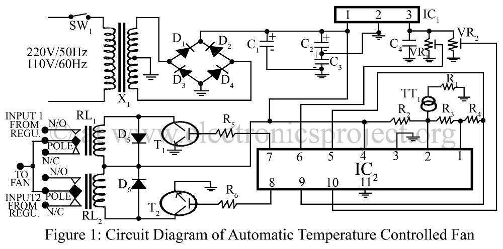
Automatic Temperature Controlled Fan
An automatic temperature-controlled fan regulates the fan speed based on temperature variations using the temperature transducer AD590 and an op-amp LM324 circuit diagram.
The automatic temperature-controlled fan circuit utilizes the AD590 temperature transducer, which provides an output voltage that is linearly...

Differential Temperature Sensor
A differential temperature sensor is employed to measure the temperature difference between two distinct areas. The schematic diagram of the circuit is provided for reference.
The differential temperature sensor circuit typically consists of two temperature sensing elements, such as thermocouples or...

Digital-ProfiLab 4.0
Digital-ProfiLab was designed for measurement and control applications, combining features like circuit and logic simulation, front panel design, and hardware control to one powerful tool. Incoming signals from external devices may be processed and displayed. A circuit editor is used...

Simple Temperature Controller
This temperature controller utilizes an LM135/235/335 temperature sensor and is designed to maintain a small environment at a warm or hot temperature. A schematic diagram is provided.
The temperature controller circuit is centered around the LM135/235/335 series of temperature sensors, which...

IN148 diode temperature measurement circuit
A diode IN4148 temperature circuit is presented. The circuit operates within a temperature range of -25 to 125 degrees Celsius, with an accuracy of 0.5. The core components of the operational amplifier circuit consist of four LMC660 amplifiers. It features...