


Bearing fault detector circuit diagram 1
#bearing detection
#signal processing
#transistor
#audio amplifier
#sensitivity adjustment
#light-emitting diode
#speaker
#RC element
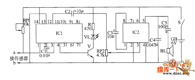
Description: The bearing fault detector circuit consists of a bearing detection sensor, a signal processing circuit, a transistor (V), an audio amplifier integrated circuit (IC2), a speaker (BL), an RC element, an integrated circuit (IC1), and a light-emitting diode (VL). The circuit also includes a transistor. RP1 is utilized to adjust the sensitivity of the signal processing circuit, while RP2 is employed for further adjustments.
The bearing fault detector circuit is designed to monitor the condition of bearings in machinery, ensuring that any faults are detected early to prevent further damage. The core component of this circuit is the bearing detection sensor, which senses vibrations or anomalies in the bearing's operation. This sensor outputs a signal that is processed by the signal processing circuit, which enhances the signal for better analysis.
The transistor (V) plays a crucial role in amplifying the processed signal to a level suitable for further processing or output. The audio amplifier integrated circuit (IC2) then amplifies this signal to drive the speaker (BL), which produces an audible alert when a fault is detected. The light-emitting diode (VL) serves as a visual indicator, providing a clear signal to operators when an issue arises.
The RC element is used to filter out noise and stabilize the circuit, ensuring that only relevant signals are processed. The integrated circuit (IC1) may include additional processing capabilities, such as signal conditioning or further amplification.
The adjustable resistors, RP1 and RP2, allow for fine-tuning of the circuit's sensitivity and response characteristics. RP1 adjusts the sensitivity of the signal processing circuit, enabling the detection of faults at varying thresholds, while RP2 provides additional adjustment capabilities to optimize performance based on specific operational conditions.
Overall, this bearing fault detector circuit is an essential tool for predictive maintenance in industrial applications, enhancing the reliability and efficiency of machinery by providing timely alerts of potential bearing failures.The bearing fault detector circuit is composed of the bearing detection sensor, signal processing circuit, transistor V, audio amplifier integrated circuit IC2, speaker BL and the RC element, and IC1, light-emitting diode VL, transistor are shown as the chart. RP1 is used to adjust the sensitivity of the signal processing circuit. RP2 is used to adjust the s..
The bearing fault detector circuit is designed to monitor the condition of bearings in machinery, ensuring that any faults are detected early to prevent further damage. The core component of this circuit is the bearing detection sensor, which senses vibrations or anomalies in the bearing's operation. This sensor outputs a signal that is processed by the signal processing circuit, which enhances the signal for better analysis.
The transistor (V) plays a crucial role in amplifying the processed signal to a level suitable for further processing or output. The audio amplifier integrated circuit (IC2) then amplifies this signal to drive the speaker (BL), which produces an audible alert when a fault is detected. The light-emitting diode (VL) serves as a visual indicator, providing a clear signal to operators when an issue arises.
The RC element is used to filter out noise and stabilize the circuit, ensuring that only relevant signals are processed. The integrated circuit (IC1) may include additional processing capabilities, such as signal conditioning or further amplification.
The adjustable resistors, RP1 and RP2, allow for fine-tuning of the circuit's sensitivity and response characteristics. RP1 adjusts the sensitivity of the signal processing circuit, enabling the detection of faults at varying thresholds, while RP2 provides additional adjustment capabilities to optimize performance based on specific operational conditions.
Overall, this bearing fault detector circuit is an essential tool for predictive maintenance in industrial applications, enhancing the reliability and efficiency of machinery by providing timely alerts of potential bearing failures.The bearing fault detector circuit is composed of the bearing detection sensor, signal processing circuit, transistor V, audio amplifier integrated circuit IC2, speaker BL and the RC element, and IC1, light-emitting diode VL, transistor are shown as the chart. RP1 is used to adjust the sensitivity of the signal processing circuit. RP2 is used to adjust the s..

Non inverting audio amplifier
Non-inverting audio amplifier schematic. This non-inverting audio amplifier circuit can be utilized in multi-channel audio systems, stereo phonographs, tape recorders and players, AM-FM radio receivers, servo amplifiers, intercom systems, and automotive products. The audio amplifier described here employs two small...

Motor time division control circuit composed of transistor and NE555
Figure 2-32 (a) illustrates the time control diagram for a motor operated by switch S1. When S1 is set to position 1, the power driver circuit supplies current to the motor, enabling it to run. When S1 is switched to...

10 vpp audio amplifier circuit
A simple audio amplifier with a 10 Vpp output designed for use with the AD633 ring modulation chip. The datasheet for the chip is available, and the circuit will utilize the XR2206 function generator IC for the modulation input.
The...

Fundamentals of Electrical Engineering and Class B audio amplifier
It is advisable to obtain TIP41 and TIP42 transistors, which are closely matched NPN and PNP power transistors with dissipation ratings of 65 watts each. If a TIP41 NPN transistor is unavailable, the TIP3055 (available from Radio Shack) serves as...

Audio Car Stereo Audio Amplifier with TDA1553CQ
When a short circuit to ground occurs, causing a DC voltage across the loudspeaker to be greater than or equal to V, an integrated protection circuit activates. This circuit limits the DC voltage across the loudspeaker to a value less...

Class B audio amplifier
The closer the two transistors are matched, the better the performance. It is advisable to use TIP41 and TIP42 transistors, which are closely matched NPN and PNP power transistors with a dissipation rating of 65 watts each. If a TIP41...

Transistorized Bar-Graph Driver
A resistor network (R1 through R10) with emitter followers (Q1 and Q2) drives LED drivers (Q3 through Q7). This circuit was utilized as a "light organ" to provide visual volume indication. It can be connected to a speaker, another audio...

An adjustable bounce lighting circuit
A circuit involving oscillations is composed of a Houle Wang oscillator that utilizes a transistor configuration with components labeled Ti, n, and n, along with a composition of Q constants for the cycle. The waveform can be modified by changing...

TDA1514 audio amplifier circuit design electronic project
The TDA1514 audio amplifier circuit design is an electronic project capable of delivering high audio power output using a specialized audio integrated circuit (IC) and a few common components. Manufactured by Philips Semiconductor, the TDA1514 audio IC can provide an...