


Bee Counter Theory
#bee counter
#sensor
#debugging
#test board
#circuit design
#gates
#resistor values
#wiring
#functional units
#schematic

Description: The schematic for the Bee Counter test board includes labeled functional units for ease of discussion. This test board features the same circuitry as the larger version but is simplified to include only four gates instead of forty-four, significantly reducing debugging time and costs. It is important to note that the circuit has not yet been tested, and there is a high likelihood that it may not function as intended. However, the design is believed to be robust, even if the wiring or resistor values are slightly incorrect, or if incompatible chips have been specified.
To summarize, the 555 timer circuit (highlighted in red) generates short pulses to activate the sensor LEDs. These pulses are directed to the LED pulser circuit (shown in green), where they are distributed to two sets of four LEDs. This configuration allows for the simultaneous pulsing of four LEDs at a time (indicated in purple), which also results in pulsing any signals from the sensors. The SR latches (depicted in orange) capture recorded signals by latching any high voltage, enabling the microcontroller to read the sensor states without needing to synchronize with the LED pulsing. After the microcontroller reads the state of each latch, it resets them to prepare for the next measurement. The demultiplexer facilitates communication between the microcontroller and over 88 sensor pins, allowing for reading and resetting of each sensor with a minimal number of microcontroller pins—potentially as few as fifteen pins for forty-four sensors.
The Bee Counter test board schematic is designed with efficiency and simplicity in mind, enabling effective testing and debugging of the overall system. The 555 timer circuit serves as the timing mechanism, providing consistent pulse outputs that are critical for the operation of the sensor LEDs. The LED pulser circuit is responsible for controlling the timing and sequencing of the LED activation, ensuring that the sensors are adequately illuminated during their operational cycles.
The SR latch configuration is integral to the design, as it allows the microcontroller to capture and store sensor readings independently of the LED pulsing. This asynchronous operation is crucial for accurate data collection, as it prevents the interference of LED activation with sensor signal readings. The microcontroller's ability to reset the latches after reading ensures that the system is ready for new data, thereby maintaining a continuous flow of information.
The implementation of a demultiplexer within the circuit architecture is a strategic choice that optimizes the use of microcontroller pins. By allowing multiple sensor inputs to be managed with fewer pins, the design enhances scalability and flexibility, making it easier to expand the system in future iterations or adaptations. This careful consideration of component selection and circuit layout reflects a well-thought-out approach to designing a functional and effective Bee Counter system.Here's the schematic for my Bee Counter test board with the functional units labeled to make them easier to discuss. This test board has the same circuitry as the larger board, but with only 4 gates instead of 44 to save a TON of time and money debugging it.
I should warn you that I haven't seen it work yet, so there's nearly a 100% chance that it won't work as drawn, but I'm pretty confident the design is solid even if my wiring or resistor values are off a bit, or if I somehow specified chips that won't work together. To summarize, the 555 timer circuit (in red) puts out short pulses that will be used to pulse the sensor LEDs. The pulses are sent to the LED pulser circuit (green). There they are routed to each set of 4 LEDs (only 2 sets in this test board). This pulses the LEDs 4 at a time (purple), but this means that any signal from the sensors is pulsed as well.
The SR Latches (orange) save a recorded signal (latching any high voltage) so the microcontroller can read the sensors without synchronizing the reading with the LED pulsing. After reading the state of each latch, the microcontroller will reset each latch so they're ready to record another measurement.
The demultiplexer simply allows the microcontroller to read and write to the 88+ sensor pins (read and reset for each sensor) with a minimum number of microcontroller pins (as few as 15 pins for 44 sensors)
To summarize, the 555 timer circuit (highlighted in red) generates short pulses to activate the sensor LEDs. These pulses are directed to the LED pulser circuit (shown in green), where they are distributed to two sets of four LEDs. This configuration allows for the simultaneous pulsing of four LEDs at a time (indicated in purple), which also results in pulsing any signals from the sensors. The SR latches (depicted in orange) capture recorded signals by latching any high voltage, enabling the microcontroller to read the sensor states without needing to synchronize with the LED pulsing. After the microcontroller reads the state of each latch, it resets them to prepare for the next measurement. The demultiplexer facilitates communication between the microcontroller and over 88 sensor pins, allowing for reading and resetting of each sensor with a minimal number of microcontroller pins—potentially as few as fifteen pins for forty-four sensors.
The Bee Counter test board schematic is designed with efficiency and simplicity in mind, enabling effective testing and debugging of the overall system. The 555 timer circuit serves as the timing mechanism, providing consistent pulse outputs that are critical for the operation of the sensor LEDs. The LED pulser circuit is responsible for controlling the timing and sequencing of the LED activation, ensuring that the sensors are adequately illuminated during their operational cycles.
The SR latch configuration is integral to the design, as it allows the microcontroller to capture and store sensor readings independently of the LED pulsing. This asynchronous operation is crucial for accurate data collection, as it prevents the interference of LED activation with sensor signal readings. The microcontroller's ability to reset the latches after reading ensures that the system is ready for new data, thereby maintaining a continuous flow of information.
The implementation of a demultiplexer within the circuit architecture is a strategic choice that optimizes the use of microcontroller pins. By allowing multiple sensor inputs to be managed with fewer pins, the design enhances scalability and flexibility, making it easier to expand the system in future iterations or adaptations. This careful consideration of component selection and circuit layout reflects a well-thought-out approach to designing a functional and effective Bee Counter system.Here's the schematic for my Bee Counter test board with the functional units labeled to make them easier to discuss. This test board has the same circuitry as the larger board, but with only 4 gates instead of 44 to save a TON of time and money debugging it.
I should warn you that I haven't seen it work yet, so there's nearly a 100% chance that it won't work as drawn, but I'm pretty confident the design is solid even if my wiring or resistor values are off a bit, or if I somehow specified chips that won't work together. To summarize, the 555 timer circuit (in red) puts out short pulses that will be used to pulse the sensor LEDs. The pulses are sent to the LED pulser circuit (green). There they are routed to each set of 4 LEDs (only 2 sets in this test board). This pulses the LEDs 4 at a time (purple), but this means that any signal from the sensors is pulsed as well.
The SR Latches (orange) save a recorded signal (latching any high voltage) so the microcontroller can read the sensors without synchronizing the reading with the LED pulsing. After reading the state of each latch, the microcontroller will reset each latch so they're ready to record another measurement.
The demultiplexer simply allows the microcontroller to read and write to the 88+ sensor pins (read and reset for each sensor) with a minimum number of microcontroller pins (as few as 15 pins for 44 sensors)

Suzuki Wiring Diagrams
Do not forget to seal your wire splices with heat shrink tubing. It provides tensile strength to wires, is flame-retardant, and protects against fraying. Heat shrink tubing forms a protective, insulated, water-resistant covering over wiring splices, crimp terminals, and solder...

Esquire Wiring
The most likely issue with the wiring is the individual responsible for it. Apologies for the lengthy post, but providing more information and pictures may help clarify the situation.
To create a comprehensive electronic schematic description, it is essential to focus...

Automatic Room light Control With Bi Directional Visitor Counter
The objective of this project is to create a controller-based model that counts the number of individuals entering a specific room and activates the lighting accordingly. This is achieved through the use of sensors that detect the current number of...
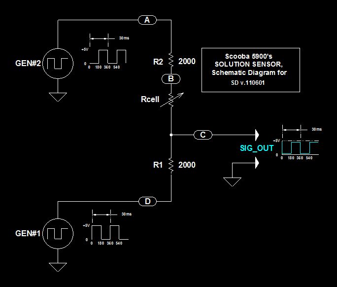
Scoobas Solution Sensing Tactic
This document serves multiple purposes, primarily to document the methods employed by a Scooba robot to detect: a) the presence of an acceptable cleaning solution being delivered to its pump, and b) the excess presence of used solution collected off...

Sensor-Activated Relay Pulser Circuit
A sensor activates transistor Q1 to turn on the low-frequency 555 oscillator, which generates pulses to control LAMP II. The sensor may respond to variations in light or temperature. Either resistor RA or RB can function as the sensor, depending...

1964 xm
I am wiring up my 1964 XM and am unsure where the wires connect for the temperature gauge. On the back of the gauge, there are labels I, S, and A. The wires are colored Green/Black, Red/White, and Yellow/Blue. Do...

1994 Golf GTI wiring
I have purchased and sold 10 MK3 Jettas and 1 MK3 Golf. This is my first time posting on a forum. I paid $400 for a 1994 GTI with the intention of fixing it and reselling it. The car was...
schematic diagram graphic arts
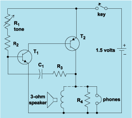
Schematic diagram. A presentation of the element-by-element relationship of all parts of a system.
A schematic diagram serves as a crucial tool in electronic design and engineering, representing the interconnections and relationships between various components within a system. It provides a...

Gate automatic lamp circuit
The circuit utilizes multiple integrated circuits to form an automatic lighting device that is activated by door and window sensors. It includes CD4093 digital integrated circuits, a relay, and a power supply circuit. The system typically remains closed when a...