


Biosensor circuit
#biosensor
#PCB design
#schematic
#sensor interface
#electronics design
#tutorials
#user interface
#circuit simulation
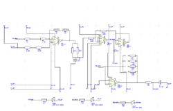
Description: This week involved the completion of several objectives. Initially, software was downloaded to design the schematic for a circuit intended for translation onto a PCB. A significant portion of the week was dedicated to tutorials and familiarization with the user interface to create an aesthetically pleasing circuit. Additionally, the circuit, which includes switches for the batteries and a DIP switch for resistance control, was submitted to the Biomedical Technology Workshop for manufacturing into a case. This will serve as the first prototype (not the PCB), and efforts were made to ensure its visual appeal.
The circuit design process began with the selection of an appropriate software tool that facilitates schematic creation and PCB layout. The chosen software allows for intuitive manipulation of components and wiring, enabling the designer to effectively visualize and implement the circuit's functionality. The design incorporates essential elements such as resistors, capacitors, and operational amplifiers, which are critical for the intended application.
The inclusion of battery switches is a key feature, providing the ability to easily disconnect the power source when the circuit is not in use, thereby extending battery life and enhancing safety. The DIP switch serves as a versatile control mechanism, allowing for the adjustment of resistance values in the circuit. This adaptability is crucial for testing and optimizing circuit performance under various conditions.
Once the schematic was finalized, the design was prepared for manufacturing. The Biomedical Technology Workshop was engaged for the fabrication of a prototype case, which serves not only a protective function but also contributes to the overall design aesthetics. Careful consideration was given to the case design to ensure it is visually appealing while maintaining functionality. This prototype will facilitate further testing and validation of the circuit's performance before proceeding to the PCB stage, thus ensuring that all design objectives are met effectively.This week was spent completing a number of different objectives. Firstly, the software was downloaded to design the schematic for the circuit to be translated onto a PCB. Much of the week was spent doing tutorials and learning the user interface to make a nice circuit. Also, the circuit, complete with switches for the batteries as well as a DIP switch to control resistance, was given to the Biomedical Technology Workshop for manufacturing into a case. This will serve as the first prototype (not the PCB), and steps were taken in order to ensure it was pleasing to the eyes.
The circuit design process began with the selection of an appropriate software tool that facilitates schematic creation and PCB layout. The chosen software allows for intuitive manipulation of components and wiring, enabling the designer to effectively visualize and implement the circuit's functionality. The design incorporates essential elements such as resistors, capacitors, and operational amplifiers, which are critical for the intended application.
The inclusion of battery switches is a key feature, providing the ability to easily disconnect the power source when the circuit is not in use, thereby extending battery life and enhancing safety. The DIP switch serves as a versatile control mechanism, allowing for the adjustment of resistance values in the circuit. This adaptability is crucial for testing and optimizing circuit performance under various conditions.
Once the schematic was finalized, the design was prepared for manufacturing. The Biomedical Technology Workshop was engaged for the fabrication of a prototype case, which serves not only a protective function but also contributes to the overall design aesthetics. Careful consideration was given to the case design to ensure it is visually appealing while maintaining functionality. This prototype will facilitate further testing and validation of the circuit's performance before proceeding to the PCB stage, thus ensuring that all design objectives are met effectively.This week was spent completing a number of different objectives. Firstly, the software was downloaded to design the schematic for the circuit to be translated onto a PCB. Much of the week was spent doing tutorials and learning the user interface to make a nice circuit. Also, the circuit, complete with switches for the batteries as well as a DIP switch to control resistance, was given to the Biomedical Technology Workshop for manufacturing into a case. This will serve as the first prototype (not the PCB), and steps were taken in order to ensure it was pleasing to the eyes.

Pulsonix PCB
Innovative yet easy-to-use PCB design editor. Includes many leading edge features for the casual and professional designer alike. Pulsonix contains a complete set of tools for designing Schematics and PCB designs in one integrated interface. Able to import many other...

McCAD PCB software
McCAD E.D.S software, a complete family of integrated electronic designs systems for MS Windows and Macintosh OS platforms. McCAD Electronic Design Systems offer a choice of design environments with a wide range of system configurations tailored to the specific needs...

EAGLE PCB Layout Editor
The EAGLE Layout Editor is an easy to use, yet powerful tool for designing printed circuit boards (PCBs). The name EAGLE is an acronym, which stands for: online Forward- and Back-Annotation, context-sensitive help function. More: no hardware copy protection! multiple...
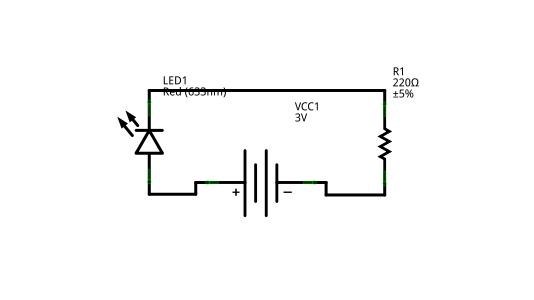
fritzing circuit
Creating circuit boards can be a challenging task. It requires designing a schematic, testing it on a breadboard, laying out the board, and finally printing and etching the board. Fortunately, Fritzing offers a solution. Fritzing is a free, open-source PCB...
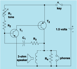
schematic diagram graphic arts
Schematic diagram. A presentation of the element-by-element relationship of all parts of a system.
A schematic diagram serves as a crucial tool in electronic design and engineering, representing the interconnections and relationships between various components within a system. It provides a...
McCAD PCB software
McCAD E.D.S software, a complete family of integrated electronic designs systems for MS Windows and Macintosh OS platforms. McCAD Electronic Design Systems offer a choice of design environments with a wide range of system configurations tailored to the specific needs...

WinCircuit
WinCircuit is a software of realization of drawing of printed circuit in single or double layers. Principal qualities are the facility of use and the sight in pseudo 3D which gets a vision of the circuit close to reality. More:...
EAGLE PCB Layout Editor
The EAGLE Layout Editor is an easy to use, yet powerful tool for designing printed circuit boards (PCBs). The name EAGLE is an acronym, which stands for: online Forward- and Back-Annotation, context-sensitive help function. More: no hardware copy protection! multiple...

Sprint-Layout
Design your own Printed Circuit Boards Sprint-Layout is a simple but powerful tool to create layouts for single-sided and double-sided PCBs (Printed Circuit Boards). More: The software comes along with all functions that are necessary for board design. Even professional...