


Bowling Game
#optointerruptor
#transistor
#74HC14
#Schmitt trigger
#digital signal
#penny detector
#current sensing
#Port M5

Description: This circuit is designed to detect the insertion of a penny. Prior to the penny being inserted, current flows through the detector side of the optointerruptor, resulting in Port M5 being high. When the penny obstructs the optointerruptor, Port M5 transitions to low. A hex inverter with a Schmitt trigger (74HC14) is employed to provide a clean digital signal ranging from 0 to 5 V. The typical positive-going threshold for the 74HC14 is 2.38 V, while the negative-going threshold is 1.40 V. This simple switch circuit outputs high when the switch is activated and low when it is not. The resistance value has been selected to ensure that the current through the switch does not exceed safe limits, with a maximum current of approximately 18.5 mA, which is within the switch's specifications. This circuit serves as an analog input to the A/D controller in the C32, facilitating the selection of the game's difficulty level. A high total resistance was chosen because the potentiometer is utilized solely as a voltage reference and does not need to source or sink significant current. A voltage divider is connected to the high side of the potentiometer, as the A/D port of the C32 accurately reads voltage values only up to about 2 V. Additionally, this circuit is responsible for activating the solenoid. When Port AD5 is high, current flows through the solenoid, activating it. The IRLZ34N transistor is selected for its capability to handle a maximum drain-to-source voltage of 55 V and a current of up to 30 A. The solenoid's resistance is 2 ohms, the internal resistance of the IRLZ34N is 0.035 ohms, and the power resistor is 10 ohms, resulting in a current of 1.08 A through the solenoid. The buzzer is activated when Port AD6 is high. The 2N7000 MOSFET is utilized due to the relatively low current in this circuit (the buzzer's resistance is 250 kΩ). To activate the buzzer, Port AD6 is pulsed high/low several times near the buzzer's resonant frequency and then held high for the desired duration. This pulsing is necessary to ensure reliable activation of the buzzer. The circuit also controls the score display, consisting of three seven-segment displays governed by three binary-coded-decimal (BCD) counters, which manage each display individually. The counters are cascaded to count up to 999 while using only two output ports from the microcontroller. The BCD counters receive clock pulses from Port M1, causing them to count to the desired number. Port M0 serves as the CLEAR bit, held high until a display reset is needed, at which point it is pulsed low. The BCD counters connect to BCD-to-seven-segment decoders that convert the four-bit BCD numbers into the corresponding seven-segment LED configuration, which are then linked to common-anode seven-segment LED displays. Resistance values of 330 ohms were selected to provide an adequate current to the display segments, ensuring they are clearly visible. The countdown timer circuit mirrors the score circuit, but utilizes only one stage of BCD counter, BCD-to-seven-segment decoder, and seven-segment LED. The switch circuit employs optointerruptors similar to those in the penny insertion sensor, with identical components and functionality, each switch being monitored by its own microcontroller port. Furthermore, this circuit utilizes two serial-in/parallel-out shift registers (74LS164) to manage 16 distinct LEDs. These LEDs serve to illuminate the bowling pins, indicate the number of attempts remaining, and display hits or misses. The shift registers are interconnected, allowing all 16 LEDs to be controlled using only two microprocessor ports. The desired output configuration is input into the first shift register's serial input from Port AD3, and it is shifted to the subsequent parallel shift register port each time the clock is pulsed (Port AD4) until the appropriate LEDs are lit. The shifting occurs rapidly, rendering it imperceptible to the human eye.
This circuit integrates multiple functional components to create an interactive gaming experience. The penny detection mechanism relies on an optointerruptor, which provides a reliable method for sensing the presence of a physical object. The use of a hex inverter with a Schmitt trigger ensures that the signal transitions are clean and free from noise, which is critical in digital circuits. The design of the switch circuit prioritizes safety by limiting the current to a manageable level, which is essential for the longevity and reliability of the components involved.
The analog input to the A/D controller is a crucial aspect of the game, allowing for dynamic interaction based on user input. The selection of appropriate resistance values in the potentiometer configuration ensures that the system can accurately interpret voltage levels, enhancing the responsiveness of the game.
The solenoid activation circuit demonstrates the ability to control high-power devices using low-power microcontroller outputs, facilitated by the IRLZ34N transistor. This design choice reflects an understanding of power management and component specifications, ensuring that the solenoid operates effectively without exceeding its rated limits.
The buzzer activation circuit showcases the use of pulsing techniques to achieve reliable sound generation, which is important for user feedback in gaming applications. The careful selection of the MOSFET for this circuit indicates a consideration of current limitations, ensuring that the buzzer operates correctly without risk of damage.
The score display and countdown timer circuits are designed for efficient operation, utilizing BCD counters and decoders to minimize the number of microcontroller ports required. This cascading approach allows for expanded functionality without overwhelming the microcontroller's capabilities.
The integration of shift registers to control multiple LEDs exemplifies a sophisticated approach to managing visual feedback in the game, ensuring that players receive clear and immediate indications of their actions. The rapid shifting of data between registers is a testament to the design's efficiency, providing a seamless user experience. Overall, this circuit represents a well-thought-out design that balances functionality, safety, and user interaction in an engaging gaming environment.This circuit is used to sense the insertion of a penny. Before the penny is inserted, current is flowing through the detector (transistor) side of the optointerruptor, and Port M5 is HI. When the penny blocks the optointerruptor, Port M5 goes low. The hex inverter with Schmitt trigger (74HC14) ensures a clean digital signal from 0 to 5 V. The typi cal positive going threshold for the 74HC14 is 2. 38 V, while the negative going threshold is 1. 40 V. This simple switch circuit outputs high when the switch is pressed and low when the switch is not pressed. The resistance value was chosen so that the current through the switch wasnot too high. The maximum current is approximately 18. 5 mA, which is within the limits of the switch. This circuit is used as an analog input to the A/D controller in the C32. It is used to select the difficulty level of the game. A large total resistance was chosen because the potentiometer is only being used as a voltage reference, so it does not need to source or sink much current.
A voltage divider was tied to the high side of the potentiometer because the A/D port of the C32 only accurately read voltage values up to about 2 V. This circuit is used to activate the solenoid. When Port AD5 is high, current runs through the solenoid and it is activated. The IRLZ34N was chosen as the transistor because it is able to tolerate a maximum drain-to-source voltage of 55 V, and up to 30 A of current.
The resistance of the solenoid is 2 ©, the internal resistance of the IRLZ34N is 0. 035 ©, and the power resistor is 10 ©, so the current through the solenoid is 1. 08 A. The buzzer is activated when Port AD6 is high. The 2N7000 MOSFET is used because the current in this circuit is not too high (the resistance of the buzzer is 250 K). To activate the buzzer, Port AD6 is pulsed high/low a few times near the buzzer`s resonant frequency, and then left high for the desired length of time.
The pulsing is needed to ensure that the buzzer will always turn on when desired. This circuit is used to control the score display. It consists of three seven-segment displays controlled by three binary-coded-decimal (BCD) counters, which individually control each display. They are cascaded together so that we can count up to 999 while using onlytwo output ports from the microcontroller.
The BCD counters are driven with a set of clock pulses from Port M1, which causes them to count up to the desired number. Port M0 is the ~CLEAR bit, which is held high until the display needs to be cleared, when it is pulsed low.
The BCD counters are connected to BCD-to-seven-segment decoders, which translate the four-bit BCD numbers into the seven-segment LED configuration. These are then connected into common-anode seven-segment LED displays. The resistance values were chosen to be 330 © because this gives a reasonable amount of current to the display segments so they are clearly visible.
The countdown timer circuit is identical to the score circuit, except it only uses one stage of BCD counter, BCD-to-seven-segment decoder, and seven-segment LED. The switch circuit uses optointerruptors just as in the penny insertion sensor. Their components and functionality is identical to that circuit, and each switch is read in by its own port of the microcontroller.
This circuit uses two serial in/parallel out shift registers (74LS164) to control 16 separate LEDs. These LEDs are used to light the bowling pins, indicate number of tries remaining, and display a hit or a miss. The shift registers are linked together so that all 16 LEDs can be controlled using only two microprocessor ports.
The desired output configuration is input to the first shift register`s serial input from Port AD3, and it is shifted to the next parallel shift register port each time the clock is pulsed (Port AD4), until the correct LEDs are lit. The shifting is done very rapidly so that it is not visible to the human eye. The 3
This circuit integrates multiple functional components to create an interactive gaming experience. The penny detection mechanism relies on an optointerruptor, which provides a reliable method for sensing the presence of a physical object. The use of a hex inverter with a Schmitt trigger ensures that the signal transitions are clean and free from noise, which is critical in digital circuits. The design of the switch circuit prioritizes safety by limiting the current to a manageable level, which is essential for the longevity and reliability of the components involved.
The analog input to the A/D controller is a crucial aspect of the game, allowing for dynamic interaction based on user input. The selection of appropriate resistance values in the potentiometer configuration ensures that the system can accurately interpret voltage levels, enhancing the responsiveness of the game.
The solenoid activation circuit demonstrates the ability to control high-power devices using low-power microcontroller outputs, facilitated by the IRLZ34N transistor. This design choice reflects an understanding of power management and component specifications, ensuring that the solenoid operates effectively without exceeding its rated limits.
The buzzer activation circuit showcases the use of pulsing techniques to achieve reliable sound generation, which is important for user feedback in gaming applications. The careful selection of the MOSFET for this circuit indicates a consideration of current limitations, ensuring that the buzzer operates correctly without risk of damage.
The score display and countdown timer circuits are designed for efficient operation, utilizing BCD counters and decoders to minimize the number of microcontroller ports required. This cascading approach allows for expanded functionality without overwhelming the microcontroller's capabilities.
The integration of shift registers to control multiple LEDs exemplifies a sophisticated approach to managing visual feedback in the game, ensuring that players receive clear and immediate indications of their actions. The rapid shifting of data between registers is a testament to the design's efficiency, providing a seamless user experience. Overall, this circuit represents a well-thought-out design that balances functionality, safety, and user interaction in an engaging gaming environment.This circuit is used to sense the insertion of a penny. Before the penny is inserted, current is flowing through the detector (transistor) side of the optointerruptor, and Port M5 is HI. When the penny blocks the optointerruptor, Port M5 goes low. The hex inverter with Schmitt trigger (74HC14) ensures a clean digital signal from 0 to 5 V. The typi cal positive going threshold for the 74HC14 is 2. 38 V, while the negative going threshold is 1. 40 V. This simple switch circuit outputs high when the switch is pressed and low when the switch is not pressed. The resistance value was chosen so that the current through the switch wasnot too high. The maximum current is approximately 18. 5 mA, which is within the limits of the switch. This circuit is used as an analog input to the A/D controller in the C32. It is used to select the difficulty level of the game. A large total resistance was chosen because the potentiometer is only being used as a voltage reference, so it does not need to source or sink much current.
A voltage divider was tied to the high side of the potentiometer because the A/D port of the C32 only accurately read voltage values up to about 2 V. This circuit is used to activate the solenoid. When Port AD5 is high, current runs through the solenoid and it is activated. The IRLZ34N was chosen as the transistor because it is able to tolerate a maximum drain-to-source voltage of 55 V, and up to 30 A of current.
The resistance of the solenoid is 2 ©, the internal resistance of the IRLZ34N is 0. 035 ©, and the power resistor is 10 ©, so the current through the solenoid is 1. 08 A. The buzzer is activated when Port AD6 is high. The 2N7000 MOSFET is used because the current in this circuit is not too high (the resistance of the buzzer is 250 K). To activate the buzzer, Port AD6 is pulsed high/low a few times near the buzzer`s resonant frequency, and then left high for the desired length of time.
The pulsing is needed to ensure that the buzzer will always turn on when desired. This circuit is used to control the score display. It consists of three seven-segment displays controlled by three binary-coded-decimal (BCD) counters, which individually control each display. They are cascaded together so that we can count up to 999 while using onlytwo output ports from the microcontroller.
The BCD counters are driven with a set of clock pulses from Port M1, which causes them to count up to the desired number. Port M0 is the ~CLEAR bit, which is held high until the display needs to be cleared, when it is pulsed low.
The BCD counters are connected to BCD-to-seven-segment decoders, which translate the four-bit BCD numbers into the seven-segment LED configuration. These are then connected into common-anode seven-segment LED displays. The resistance values were chosen to be 330 © because this gives a reasonable amount of current to the display segments so they are clearly visible.
The countdown timer circuit is identical to the score circuit, except it only uses one stage of BCD counter, BCD-to-seven-segment decoder, and seven-segment LED. The switch circuit uses optointerruptors just as in the penny insertion sensor. Their components and functionality is identical to that circuit, and each switch is read in by its own port of the microcontroller.
This circuit uses two serial in/parallel out shift registers (74LS164) to control 16 separate LEDs. These LEDs are used to light the bowling pins, indicate number of tries remaining, and display a hit or a miss. The shift registers are linked together so that all 16 LEDs can be controlled using only two microprocessor ports.
The desired output configuration is input to the first shift register`s serial input from Port AD3, and it is shifted to the next parallel shift register port each time the clock is pulsed (Port AD4), until the correct LEDs are lit. The shifting is done very rapidly so that it is not visible to the human eye. The 3

Direct Coupled Discrete Astable Multivibrator circuit
This flip-flop circuit functions as a free-running astable multivibrator, where the bases and collectors of both emitter-biased transistors are directly coupled. The switching action is facilitated by a capacitor in each emitter circuit, resulting in the generation of triangle waves...

Anti-saturation function delete circuit schematics
Anti-saturation devices have been removed from the UAA4002 routine applications. The base current of the switching transistor, which is driven by another transistor, is automatically adjusted. This adjustment allows the power transistors to operate in critical saturation. However, when the...

Power amplifier using transistors
A high-power audio amplifier can be designed using power transistors and other common electronic components, capable of delivering a maximum output power of 90W. When using the specified component values, it can drive speakers with a 4-ohm impedance, resulting in...
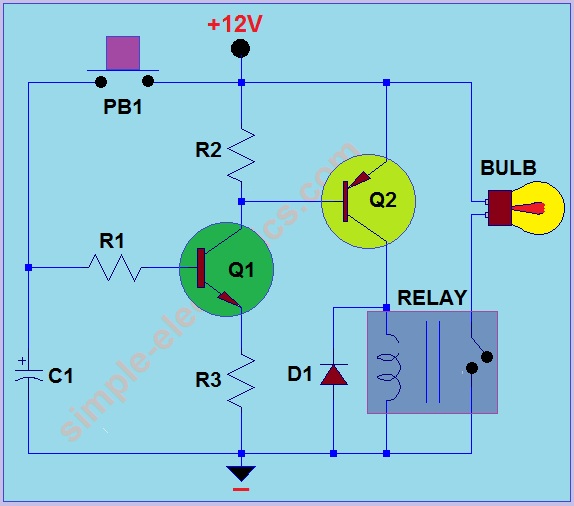
Car Headlight with Delay Circuit
This circuit operates by activating a headlight when the push-button PB1 is pressed. The headlight remains illuminated for a predetermined duration, which can range from several seconds to minutes, before automatically turning off. When PB1 is engaged, capacitor C1 begins...
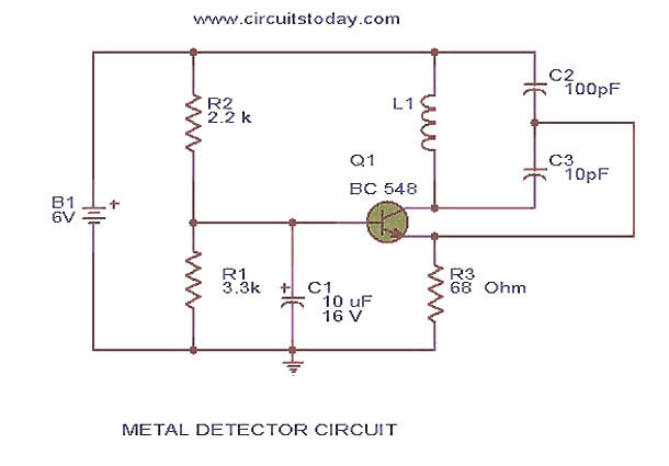
metal detector circuit
This circuit diagram represents a low-cost metal detector utilizing a single transistor circuit in conjunction with an old pocket radio. It operates as a Colpitts oscillator functioning within the medium band frequency range, with the radio tuned to the same...

Transistor Circuits
It had been a little over a decade since the invention of the transistor when this article appeared in the August 1959 edition of Popular Electronics. Transistors were still a mystery to many, including engineers, technicians, and hobbyists. Author James...

voltage transistor loop to limit the current
The second transistor (T2) is activated by the current passing through the resistor (R1). When a DALI slave unit is connected, this current matches the current flowing through the power transistor (T1). The resistor's value is selected so that when...

Transistor time relay circuit
This circuit consists of five transistor time relay circuits designed for time relay exchange. It utilizes two different power supplies, maintaining the same circuit configuration. The delay time can be adjusted by modifying a potentiometer. The parameters for the time...

Free-Electron Pump (FEP) Experiments
A simple two-transistor inverter circuit has been constructed for this experiment. The transformer depicted is the inverter transformer. The output voltage from the inverter is in the form of pulses, with an estimated peak value of approximately 700V. When a...