


Capacitive SensorCircuit
#capacitive sensor
#relay
#animation
#shop-window
#touch activation
#model trains
#toy-shop
#glass interaction
#proximity detection
#automation

Description: The purpose of this circuit is to animate shop windows using a capacitive sensor placed behind a postcard-like banner. The card is positioned against the glass inside the shop window, allowing visitors to activate the relay by placing their hand on the card from outside. This circuit is particularly suitable for toy shops, as it can activate model trains, small electric racing cars, lights, and more. Additional applications can be explored based on user creativity. It can be adapted to enhance the visual appeal of shop windows, especially during the Christmas season. Q1, Q2, and Q3 form a high-impedance super-Darlington configuration that drives the relay, amplifying the 50 or 60Hz alternating mains supply frequency induced in the sensor by the human body. C1, D2, and D3 ensure clean relay switching. The power supply can be any commercial wall plug-in transformer adapter with a rectifier and smoothing capacitor, capable of providing the necessary voltage and current to power the intended relay.
This circuit design utilizes a capacitive sensor that detects the presence of a human hand, which serves as a trigger for various animated elements in a shop window display. The capacitive sensor operates by measuring changes in capacitance caused by the proximity of a conductive object, such as a human hand. When the hand approaches the postcard-like banner, the sensor detects the change and activates the relay.
The high-impedance super-Darlington configuration formed by transistors Q1, Q2, and Q3 is crucial for amplifying the small signals generated by the sensor. This configuration allows for a significant increase in current gain, enabling the circuit to drive larger loads, such as relays, without requiring substantial input current. The use of a super-Darlington arrangement enhances the sensitivity and response time of the circuit, making it highly effective for shop window applications.
Capacitor C1, along with diodes D2 and D3, plays an essential role in ensuring that the relay operates smoothly and without bouncing. C1 acts as a filter to stabilize the voltage at the relay's coil, while D2 and D3 protect against back EMF generated when the relay is de-energized, preventing potential damage to the circuit components.
The power supply for this circuit is flexible, allowing for the use of a standard wall plug-in transformer adapter. This adapter must be equipped with a rectifier and smoothing capacitor to convert the AC mains supply into a stable DC voltage suitable for the relay and other circuit components. The selection of the power supply should consider the voltage and current ratings required by the specific relay being used, ensuring reliable operation of the overall circuit.
In summary, this circuit provides an innovative method for animating shop windows, leveraging capacitive sensing technology to engage customers and enhance the shopping experience. Its versatility allows for various creative applications, making it an excellent choice for seasonal promotions and retail displays.The purpose of this circuit is to animate shop-windows by means of a capacitive sensor placed behind a post-card-like banner. The card is placed against the glass inside the shop-window, and the visitor can activate the relay placing his hand on the card, from the outside.
Especially suited for toy-shops, the circuit can activate model trains, sma ll electric racing cars, lights etc. Further applications are left at user`s imagination. Adopt it to increase the impact of your shop-window on next Christmas season! Q1, Q2 & Q3 form a high impedance super-Darlington that drives the relay, amplifying the 50 or 60Hz alternate mains-supply frequency induced in the sensor by the human body. C1, D2 & D3 ensure a clean switching of the relay. Power supply can be any commercial wall plug-in transformer adapter with rectifier and smoothing capacitor, capable of supplying the voltage and current necessary to power the relay you intend to use.
This circuit design utilizes a capacitive sensor that detects the presence of a human hand, which serves as a trigger for various animated elements in a shop window display. The capacitive sensor operates by measuring changes in capacitance caused by the proximity of a conductive object, such as a human hand. When the hand approaches the postcard-like banner, the sensor detects the change and activates the relay.
The high-impedance super-Darlington configuration formed by transistors Q1, Q2, and Q3 is crucial for amplifying the small signals generated by the sensor. This configuration allows for a significant increase in current gain, enabling the circuit to drive larger loads, such as relays, without requiring substantial input current. The use of a super-Darlington arrangement enhances the sensitivity and response time of the circuit, making it highly effective for shop window applications.
Capacitor C1, along with diodes D2 and D3, plays an essential role in ensuring that the relay operates smoothly and without bouncing. C1 acts as a filter to stabilize the voltage at the relay's coil, while D2 and D3 protect against back EMF generated when the relay is de-energized, preventing potential damage to the circuit components.
The power supply for this circuit is flexible, allowing for the use of a standard wall plug-in transformer adapter. This adapter must be equipped with a rectifier and smoothing capacitor to convert the AC mains supply into a stable DC voltage suitable for the relay and other circuit components. The selection of the power supply should consider the voltage and current ratings required by the specific relay being used, ensuring reliable operation of the overall circuit.
In summary, this circuit provides an innovative method for animating shop windows, leveraging capacitive sensing technology to engage customers and enhance the shopping experience. Its versatility allows for various creative applications, making it an excellent choice for seasonal promotions and retail displays.The purpose of this circuit is to animate shop-windows by means of a capacitive sensor placed behind a post-card-like banner. The card is placed against the glass inside the shop-window, and the visitor can activate the relay placing his hand on the card, from the outside.
Especially suited for toy-shops, the circuit can activate model trains, sma ll electric racing cars, lights etc. Further applications are left at user`s imagination. Adopt it to increase the impact of your shop-window on next Christmas season! Q1, Q2 & Q3 form a high impedance super-Darlington that drives the relay, amplifying the 50 or 60Hz alternate mains-supply frequency induced in the sensor by the human body. C1, D2 & D3 ensure a clean switching of the relay. Power supply can be any commercial wall plug-in transformer adapter with rectifier and smoothing capacitor, capable of supplying the voltage and current necessary to power the relay you intend to use.

motorcycle alarms numbers
These are two easy-to-build relay-based alarms that can be used to protect motorcycles, among other applications. Using relays with 6-volt coils will safeguard a "Classic Bike." Both alarms are compact, with completed boards occupying approximately half a cubic inch (8...

Coop automatic controller circuit diagram
The automatic controller for a chicken coop is designed to automatically regulate light, temperature, and humidity, thereby enhancing egg production and survival rates of chickens. This device is intended for specialized poultry households in rural areas. The circuit operates through...

Controlling a relay with a digital logic level circuit
The schematic below illustrates four methods of controlling a relay with a digital logic signal. Figure A can be used in most cases where the relay coil requires 100 mA or less and the input current is 2 milliamps or...

DC relay delayed release circuit 2 b
The circuit depicted in Figure 6-24 includes a relay coil with both ends connected in parallel to a resistor (Rf) or an auxiliary diode (VD). This configuration is intended to enhance power after a short circuit occurs in the coil...

Universal Power Controller
Relay K1 features a low-impedance coil, while Relay K2 is equipped with a high-impedance coil. When a sensor opens, current flows through the coil of K1, activating it. This action opens the contacts of K1, thereby preventing the reclosure of...

chip programmer
This project originated from the need to control home heating remotely from work. Utilizing a VPN connection between work and home, a relay controlled by a PC was considered the simplest solution. However, a control unit that could be operated...

A relay control circuit
A relay control circuit is illustrated, which is commonly found in microwave switches. This circuit facilitates the operation of various components such as the power supply switch, electric fans, light bulbs, food turntables, and timers. The relay control signal circuit...
Reducing Relay Power Consumption
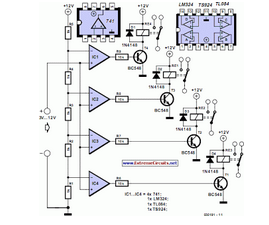
This circuit demonstrates that microprocessors, personal computers, and the latest ultra-accurate digital-to-analog converters (DACs) are excessive for the task of sequentially controlling four relays.
The circuit utilizes a simple microcontroller or a basic timer IC to manage the operation of four...

microcontroller 12V relay circuit converted to 5V relay under uC control
The BC547B transistor has a collector-base voltage (Vcbo) of 50V, a collector-emitter voltage (Vceo) of 45V, and an emitter-base voltage (Vebo) of 6V. In contrast, the BC548 transistor in the original circuit has a Vcbo of 30V, a Vceo of...