


coin detector and counter
#coin detection
#magnetic field
#counter
#oscillating circuit
#sensor
#electronics
#measurement
#DIY

Description: Coin detector and counter: How to detect different types of coins from their effect on an oscillating magnetic field.
A coin detector and counter operates by utilizing the principles of electromagnetic induction to identify and differentiate between various types of coins. The system typically consists of an oscillating magnetic field generated by an inductor or coil. When a coin enters the field, it alters the magnetic flux due to its conductive properties. This change in the magnetic field induces a current in the coin, which in turn generates its own magnetic field.
The circuit design usually includes a high-frequency oscillator to produce the oscillating magnetic field. The frequency of oscillation is chosen based on the expected properties of the coins to be detected, as different metals will interact with the magnetic field differently. The induced currents in the coins will produce varying impedance, which can be measured by a microcontroller or an analog circuit.
The detection mechanism may involve a comparator circuit that compares the impedance changes against preset thresholds corresponding to different coin types. This allows the system to distinguish between coins made of different materials, such as copper, nickel, and zinc, based on their unique electromagnetic signatures.
Furthermore, the output from the detection circuit can be interfaced with a digital counter to tally the number of coins detected. This counter can be designed to display the total value of the coins based on their types and quantities, providing a comprehensive solution for coin detection and counting in various applications, including vending machines and coin sorting systems.
In conclusion, a coin detector and counter leveraging an oscillating magnetic field is an effective electronic solution for identifying and quantifying different coin types through their electromagnetic interactions.Coin detector and counter : How to detect different types of coins from their effect on an oscillating magnetic field..
A coin detector and counter operates by utilizing the principles of electromagnetic induction to identify and differentiate between various types of coins. The system typically consists of an oscillating magnetic field generated by an inductor or coil. When a coin enters the field, it alters the magnetic flux due to its conductive properties. This change in the magnetic field induces a current in the coin, which in turn generates its own magnetic field.
The circuit design usually includes a high-frequency oscillator to produce the oscillating magnetic field. The frequency of oscillation is chosen based on the expected properties of the coins to be detected, as different metals will interact with the magnetic field differently. The induced currents in the coins will produce varying impedance, which can be measured by a microcontroller or an analog circuit.
The detection mechanism may involve a comparator circuit that compares the impedance changes against preset thresholds corresponding to different coin types. This allows the system to distinguish between coins made of different materials, such as copper, nickel, and zinc, based on their unique electromagnetic signatures.
Furthermore, the output from the detection circuit can be interfaced with a digital counter to tally the number of coins detected. This counter can be designed to display the total value of the coins based on their types and quantities, providing a comprehensive solution for coin detection and counting in various applications, including vending machines and coin sorting systems.
In conclusion, a coin detector and counter leveraging an oscillating magnetic field is an effective electronic solution for identifying and quantifying different coin types through their electromagnetic interactions.Coin detector and counter : How to detect different types of coins from their effect on an oscillating magnetic field..

Magnetic Field Meter Magnetometer Circuit
Some experts believe that static magnetic fields (SMFs) may affect the physical well-being of individuals. If one subscribes to this viewpoint, the magnetic-field meter described here will aid in locating sources of SMFs and assessing their strength. These results may...

Digital Up / Down Counter
This Circuit uses a CD40110BE, Up/Down Counter IC's. This IC is able to Source Each Segment with 25 mA, Giving a Very Nice Bright Display. The 7 Segment Displays MUST be a Common Cathode Type, as I have used here....

Odd-number-counter-divider
This circuit, illustrated symmetrically, divides an input by virtually any odd number. The circuit counts n + 1/2 clocks twice to achieve the desired divisor. By selecting the appropriate n, which is the decoded output of the LS161 counter, divisors...

Winding electronic counter 2
The electronic counter of the winding machine utilizes an LED digital display to indicate the number of turns of the wound coil, with a maximum counting capacity of 9900 turns. The operational principle of the winding machine circuit consists of...

up down counter circuit
This circuit diagram illustrates a simple up/down counter suitable for various applications. It utilizes the CD40110BE IC, a CMOS decade up/down counter. Common cathode seven-segment displays are connected to the outputs of each IC. The display connected to IC1 shows...
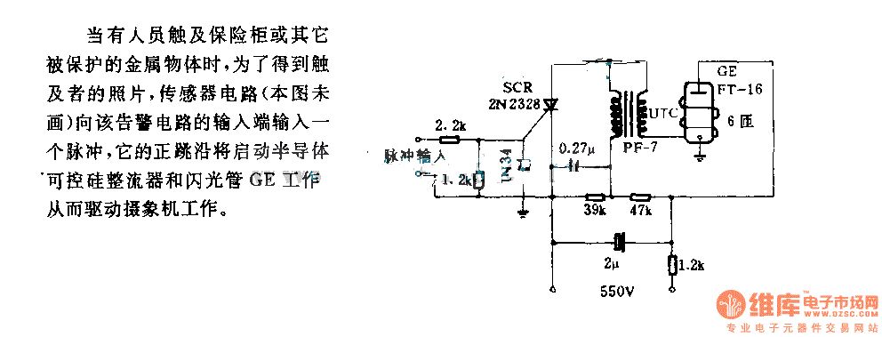
The alarm circuit diagram for safety box and other metal objects
When an individual touches the safety box or other protected metal objects, the sensor circuit generates a pulse to the alarm circuit. The positive edge of this pulse activates the semiconductor and thyristor flash GE, subsequently triggering the camera to...

Counter
This article discusses the term "counter" as it relates to electronics and computing. For additional meanings, refer to the term "Counter" in disambiguation. In digital logic and computing, a counter is a device that stores (and occasionally displays) the number...

Counter circuit diagram of the digital circuit
The digital counter circuit described utilizes an infrared signal to detect moving targets, making it suitable for counting small devices on a production line as they move along a conveyor belt. This circuit can also be employed for various other...

8-Digit up-down counter
This circuit illustrates the method of cascading counters while maintaining the appropriate leading zero blanking. A NAND gate is employed to determine if a digit is active, as indicated by the activation of either segment a or b on any...