


colours sensor detector circuit
#color sensor
#RGB detection
#digital electronics
#optical sensor
#primary colors
#secondary colors
#black and white detection
#object detection
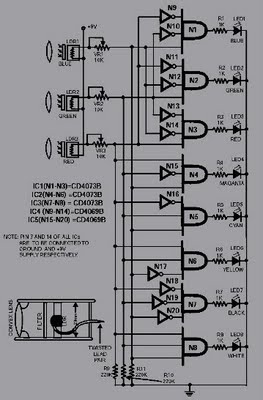
Description: This circuit is capable of sensing eight colors: blue, green, and red (primary colors); magenta, yellow, and cyan (secondary colors); along with black and white. It is designed based on the principles of optics and digital electronics. The object whose color needs to be detected must be positioned in front of the system.
The color detection circuit utilizes a combination of photodetectors and microcontrollers to accurately identify and differentiate between various colors. The primary colors are detected using RGB (Red, Green, Blue) sensors, which measure the intensity of light in each of these three wavelengths. The readings from these sensors are then processed to determine the presence of primary and secondary colors based on predefined thresholds.
For detecting black and white, the circuit employs a light intensity measurement that assesses the overall brightness of the object. When the intensity is low, the object is classified as black, while a high intensity indicates the presence of white. The circuit's design incorporates analog-to-digital converters (ADCs) to convert the analog signals from the sensors into digital data that can be processed by the microcontroller.
The microcontroller is programmed with an algorithm that compares the sensor readings against a color lookup table, enabling real-time color recognition. This allows the system to output the detected color through a display or interface, providing immediate feedback.
In terms of hardware, the circuit may include additional components such as resistors, capacitors, and LEDs for status indication. Proper calibration of the sensors is essential to ensure accuracy and reliability in various lighting conditions. Overall, this color sensing circuit serves applications in robotics, automation, and interactive systems, where color recognition is crucial for functionality.This circuit can sense eight colours, i. e. blue, green and red (primary colours); magenta, yellow and cyan (secondary colours); and black and white. The circuit is based on the fundamentals of optics and digital electronics. The object whose colour is required to be detected should be placed in front of the system.
The color detection circuit utilizes a combination of photodetectors and microcontrollers to accurately identify and differentiate between various colors. The primary colors are detected using RGB (Red, Green, Blue) sensors, which measure the intensity of light in each of these three wavelengths. The readings from these sensors are then processed to determine the presence of primary and secondary colors based on predefined thresholds.
For detecting black and white, the circuit employs a light intensity measurement that assesses the overall brightness of the object. When the intensity is low, the object is classified as black, while a high intensity indicates the presence of white. The circuit's design incorporates analog-to-digital converters (ADCs) to convert the analog signals from the sensors into digital data that can be processed by the microcontroller.
The microcontroller is programmed with an algorithm that compares the sensor readings against a color lookup table, enabling real-time color recognition. This allows the system to output the detected color through a display or interface, providing immediate feedback.
In terms of hardware, the circuit may include additional components such as resistors, capacitors, and LEDs for status indication. Proper calibration of the sensors is essential to ensure accuracy and reliability in various lighting conditions. Overall, this color sensing circuit serves applications in robotics, automation, and interactive systems, where color recognition is crucial for functionality.This circuit can sense eight colours, i. e. blue, green and red (primary colours); magenta, yellow and cyan (secondary colours); and black and white. The circuit is based on the fundamentals of optics and digital electronics. The object whose colour is required to be detected should be placed in front of the system.

Color Sensor circuit
Colour sensor is an interesting project for hobbyists. The circuit can sense eight colours, i.e. blue, green and red (primary colours); magenta, yellow and cyan (secondary colours); and black and white. The circuit is based on the fundamentals of optics...

pcb Help identifying and finding shematics/datasheets for circuit board
The chip in the center with small bullet holes is likely proprietary. It is possible to salvage a few components from it, although understanding the circuit is not necessary for this purpose. Additionally, it is confirmed that the device is...

A contact-less digital tachometer based on optical sensors
The circuit for the Digital Tachometer/RPM Counter consists of only a few devices. Wire them up according to the following circuit diagram. The PIC used is on a demonstration board, which means the clock, power, and ground pins are already...

Optical Interruption Sensor
Using only an 8-pin integrated circuit (IC) and a few discrete components, an infrared optical interrupter can be constructed. The NE567 tone decoder includes all necessary circuit elements: a local oscillator, a phase-locked loop (PLL) decoder, and a 100-mA output...

Color sensor
A color sensor is an engaging project for hobbyists. The circuit is capable of detecting eight colors, including blue, green, and red (the primary colors), as well as magenta and yellow.
The color sensor circuit typically employs a photodiode or phototransistor...
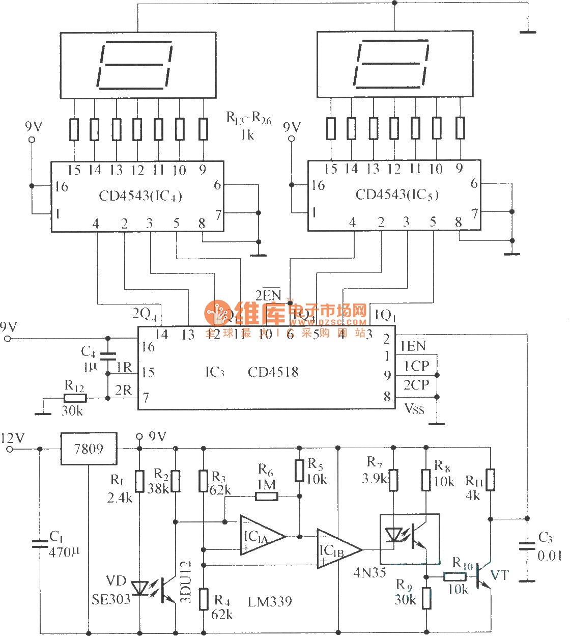
Digital displaying photoelectric counter circuit diagram
The circuit includes an optical input circuit (VD, 3DU12), a pulse forming circuit (IC1A, IC1B functioning as a voltage comparator; optical coupler; transistor switching circuit), and a counting and display circuit.
The circuit architecture consists of several key components that work...

Optical proximity detector circuit diagram
A reflex isolator detects the presence of an object by reflecting light from the object back to the sensor. This technique is effective when an object is in close proximity to the sensor.
Reflex isolators, also known as proximity sensors, utilize...
Digital displaying photoelectric counter circuit diagram
The circuit includes an optical input circuit (VD, 3DU12), a pulse forming circuit (IC1A, IC1B functioning as a voltage comparator; optical coupler; transistor switching circuit), and a counting and display circuit.
The circuit architecture consists of several key components that work...

Optical-sensor-to-ttl-interface
This circuit is designed to detect low light levels at the sensor, amplify the signal, and provide a TTL-level output. When the optical sensor detects low-level light, its output is small and must be amplified. An amplifier with very low...